
All-in-One (AIO) Integration with Thin Mini-ITX Intel Desktop Boards


AIO Integration with Thin Mini-ITX Intel® Desktop Boards – v3.0
7
3.
Connectors
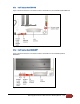
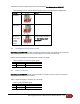
3.1 LVDS connector
The LVDS panel connector is a 40-pin (dual-row) shrouded white header, supporting video data, clock, and
EDID signals, as well as panel logic power. This connector/cable ships already built into the AIO chassis and
does not need to be purchased separately.
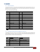
Table 2: 40-pin LVDS connector signals
Pin
Signal name
Pin
Signal name
1
ODD_Lane3_P
21
N/C
2
ODD_Lane3_N
22
EDID_3.3 V
3
ODD_Lane2_P
23
LCD_GND
4
ODD_Lane2_N
24
LCD_GND
5
ODD_Lane1_P
25
LCD_GND
6
ODD_Lane1_N
26
ODD_CLK_P
7
ODD_Lane0_P
27
ODD_CLK_N
8
ODD_Lane0_N
28
BKLT_GND
9
EVEN_Lane3_P
29
BKLT_GND
10
EVEN_Lane3_N
30
BKLT_GND
11
EVEN_Lane2_P
31
EDID_CLK
12
EVEN_Lane2_N
32
BKLT_ENABLE
13
EVEN_Lane1_P
33
BKLT_PWM_DIM
14
EVEN_Lane1_N
34
EVEN_CLK_P
15
EVEN_Lane0_P
35
EVEN_CLK_N
16
EVEN_Lane0_N
36
BKLT_PWR (12 V/19 V)
17
EDID_GND
37
BKLT_PWR (12 V/19 V)
18
LCD_VCC (3.3 V/5 V/12 V)
38
BKLT_PWR (12 V/19 V)
19
LCD_VCC (3.3 V/5 V/12 V)
39
N/C
20
LCD_VCC (3.3 V/5 V/12 V)
40
EDID_DATA
Note:
LVDS single-channel output is driven from the ODD signals.
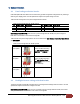
3.2 Front panel display (FPD) brightness connector
The backlight inverter power connector is an 8-pin (single-row) shrouded header, supporting backlight lamp
enable and PWM control signals as well as inverter power. This connector/cable ships already built into the
AIO chassis and does not need to be purchased separately.
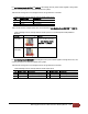
Table 3: FPD brightness connector signals
Pin
Signal name
Description
1
BKLT_EN
Backlight enable
2
BKLT_PWM
Backlight control
3
BKLT_PWR (12 V/19 V)
Backlight inverter power
4
BKLT_PWR (12 V/19 V)
Backlight inverter power
5
BKLT_GND/Brightness_GND
Ground (shared)
6
BKLT_GND/Brightness_GND
Ground (shared)
7 Brightness_Up Panel brightness increase
8
Brightness_Down
Panel brightness decrease