Intel NetStructure™ 470 Switch ® Intel ® NetStructure™ 470 Switch User Guide A18558-002 User Guide
Copyright © 2001, Intel Corporation. All rights reserved. Intel Corporation, 5200 NE Elam Young Parkway, Hillsboro OR 97124-6497 Intel Corporation assumes no responsibility for errors or omissions in this manual. Nor does Intel make any commitment to update the information contained herein. Intel is a trademark or registered trademark of Intel Corporation or its subsidiaries in the United States and other countries.
C O N T E N T S Contents Intel® NetStructure 470T and 470F Switches User Guide 1 Setting up the Intel® NetStructure™ 470T and 470F Switches Overview .......................................................................... 1 Management .................................................................... 1 Switch Features ............................................................... 2 LEDs ................................................................................
C O N T E N T S Intel® NetStructure 470T and 470F Switches User Guide 4 Using the Web Device Manager Overview .......................................................................... 27 Accessing the Web Device Manager ............................... 28 Navigating the Web Device Manager ............................... 28 Using Management Screens ............................................ 29 Configuring the Switch’s IP Settings ................................ 31 Configuring a Port ..........
C O N T E N T S Intel® NetStructure 470T and 470F Switches User Guide Configure IGMP Snooping ............................................... 65 Configure Static MAC Addresses ..................................... 66 Configure Port Security .................................................... 67 Configure MAC Address Filtering ..................................... 68 Configure Ethernet Multicast Filtering .............................. 69 Ethernet Multicast Filtering (Ports) ....................
C O N T E N T S Intel® NetStructure 470T and 470F Switches User Guide Monitor (Network Statistics) ............................................. 102 Switch Overview .............................................................. 103 Port Traffic Statistics ........................................................ 104 Port Error Statistics .......................................................... 106 Packet Analysis ................................................................
1 Setting up the Intel® NetStructure™ 470T and 470F Switches Overview This guide provides information on configuring and managing the Intel® NetStructure™ 470T and 470F Switches.
C H A P T E R 1 Intel® NetStructure™ 470T and 470F Switches User Guide Switch Features These are the major features of the 470 switches.
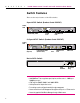
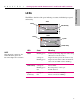
C H A P T E R 1 Setting Up the Intel® NetStructure™ 470T and 470F Switches 470 Switch Setup LEDs The LEDs to the left of the ports indicate port status, individual port speed, and activity. 470F Status Link/Activity 470T Status Speed Link/Activity NOTE After the switch is turned on, the Status LED blinks green once before the diagnostic mode starts. LED State Meaning Status Blinking green Switch is performing diagnostics and booting. (This lasts for 20–30 seconds.
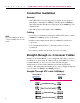
C H A P T E R 1 Intel® NetStructure™ 470T and 470F Switches User Guide Connection Guidelines General • The 470T switch is can auto-negotiate port duplex. It can operate at half-duplex or full-duplex at 100Mbps, and full-duplex at 1000Mbps. The switch matches the highest possible speed (up to 1000Mbps) of an attached device. • The 470F operates at full-duplex and at 1000Mbps. Cabling NOTE Use certified Category 5 cables to connect 1000Mbps devices to the switch.
C H A P T E R 1 Setting Up the Intel® NetStructure™ 470T and 470F Switches 470 Switch Setup Crossover UTP cable (100Mbps) Switch (MDI-X) Hub (MDI-X) Straight-Through UTP cable (1000Mbps) Switch (MDI) Switch (MDI) 5
C 6 H A P T E R 1 Intel® NetStructure™ 470T and 470F Switches User Guide
2 Using the Intel® NetStructure™ 470T and 470F Switches Overview Chapter 2 provides an overview for using the Intel® NetStructure™ 470T and 470F Switches within a network. This chapter covers switching features like flow control and spanning tree, and includes a discussion of the more advanced features such as link aggregation and the types of VLANs available on the switch. If you are familiar with switching technology you can skip ahead to a particular section within the chapter.
C H A P T E R 2 Intel® NetStructure™ 470T and 470F Switches User Guide Sample Configuration The following example illustrates how the 470T and 470F switches can be used in a network. In this example, the Intel NetStructure 480T Routing Switch is the backbone of the network, providing routing capability. The 470T and 470F switches provide gigabit connectivity from the 480T to the Intel Express 460T Standalone Switches through the 460T gigabit uplinks.
C H A P T E R 2 Using the Intel® NetStructure™ 470T and 470F Switches Flow Control During heavy network activity, the switch’s port buffers can receive too much traffic and fill up faster than the switch can send the information. In cases like this, the switch tells the transmitting device to wait until the information in the buffer can be sent. This traffic control mechanism is called flow control.
C H A P T E R 2 Intel® NetStructure™ 470T and 470F Switches User Guide The switch checks the amount of broadcast traffic on each port every 20 seconds. If the port detects that the amount of broadcast traffic exceeds the upper threshold on two subsequent checks, the port drops all broadcast traffic. When broadcast traffic is dropped for storm control, the switch continues to check the amount of broadcast traffic on each port.
C H A P T E R 2 Using the Intel® NetStructure™ 470T and 470F Switches In this example, Client A can communicate with Server B over two different paths. The primary path is Path 1 because the cost of the connection between switches A and C is lower than the cost between switches A, B and C. If the primary path fails, traffic is automatically sent over the backup path. Tagged Frames Some devices don’t recognize the tagged Ethernet frames.
C H A P T E R 2 Intel® NetStructure™ 470T and 470F Switches User Guide Although there are eight priority levels, the 470 switches can only put a packet into one of the two queues. The switch maps levels 0-3 to the low queue and levels 4-7 to the high queue. If a packet is untagged, the switch can be set to use either the high or low queue for that port. The 470 switches preserve the priority level of the packet.
C H A P T E R 2 Using the Intel® NetStructure™ 470T and 470F Switches Guidelines • The switch treats aggregated links as a single port. This includes spanning tree and VLAN configurations. • For the 470F: Anchor ports 1, 3, and 5 can each have up to four aggregated ports; anchor port 7 can have two. • All ports share the same settings as the anchor port. You can change anchor port settings, but you cannot configure other ports in the link.
C H A P T E R 2 Intel® NetStructure™ 470T and 470F Switches User Guide Port-based VLANs Port-based VLANs are the simplest and most common form of VLAN. In a port-based VLAN, the system administrator assigns the ports to a specific VLAN. For example, the system administrator can designate ports 1, 2, and 3 as part of the engineering VLAN and ports 5, 6, 7, and 8 as part of the marketing VLAN.
C H A P T E R 2 Using the Intel® NetStructure™ 470T and 470F Switches The 802.1Q VLAN works by using a tag added to the Ethernet frames. The tag contains a VLAN Identifier (VID) that identifies the frame as belonging to a specific VLAN. These tags allow switches that support the 802.1Q specification to segregate traffic between devices and communicate a device’s VLAN association across switches. The example below shows a 470F switch.
C H A P T E R 2 Intel® NetStructure™ 470T and 470F Switches User Guide Protocol-based VLANs In a protocol-based VLAN, traffic is bridged through specified ports based on its protocol. Any packet using a different protocol is dropped as it enters the switch. This type of VLAN allows you to use a common protocol to communicate, yet prevents any packets that are not using the specified protocol, from entering the switch.
C H A P T E R 2 Using the Intel® NetStructure™ 470T and 470F Switches Spanning Tree Protocol and VLANs The 470 switches support the Spanning Tree Protocol across the entire switch, not across each VLAN. If VLANs create a redundant link between two switches and both of those switches have the Spanning Tree Protocol enabled, one of the VLANs is disabled. GARP VLAN Registration Protocol (GVRP) Because tag-based (IEEE 802.
C H A P T E R 2 Intel® NetStructure™ 470T and 470F Switches User Guide GARP (Generic Attribute Registration Protocol) is defined by the IEEE 802.1D (1998 Edition) specification and is the mechanism used by switches and end nodes (servers, PCs, and so on) to propagate configuration across the network domain. GVRP uses GARP as a foundation to propagate VLAN configuration to other switches.
3 Using Intel® Device View Overview Intel® Device View allows you to manage Intel NetStructure™ 470T and 470F switches and other supported Intel networking devices on your network.
C H A P T E R 3 Intel® NetStructure™ 470T and 470F Switches User Guide Installing Intel Device View Before you install Intel Device View, make sure your PC meets the system requirements in the Intel® Device View User Guide, which is included on the Intel Device View CD-ROM. To install Intel Device View 1 Insert the Intel Device View CD-ROM into your computer’s CD-ROM drive. The Intel Device View installation screen appears. If it doesn’t appear, run autoplay.exe from the CD-ROM.
C H A P T E R 3 Intel Device View Starting Intel Device View Install either the Windows or Web version of Intel Device View. Windows* version On your desktop, click Start and then point to Programs > Intel Device View > Intel Device View - Windows to go to the Intel Device View main screen. Web version NOTE Web browser On your desktop, click Start and then point to Programs > Intel Device View > Intel Device View - Web to go to the Intel Device View main screen.
C H A P T E R 3 Intel® NetStructure™ 470T and 470F Switches User Guide Installing a New Switch After you install a new switch on your network, you can use the Intel Device View Device Install Wizard to configure it for management. To install and configure a new switch for management 1 Start Intel Device View. The Device Install Wizard appears. If it doesn’t appear, click Install from the Device menu or double-click the appropriate MAC address in the Device Tree under Unconfigured Devices.
C H A P T E R 3 Intel Device View Different states of the 470 switches are represented by icons in the Device Tree. Device Tree icons Device Tree root Subnet Intel Switch (if non-responding the icon is red) Unconfigured Intel Switch Intel® Device View Group of Intel Switches Intel Router Intel Switch (Layer 3 capable) Intel Stackable Hub To expand the root or a subnet, click the (+) next to the icon. To collapse the view, click the (-) next to the icon.
C H A P T E R 3 Intel® NetStructure™ 470T and 470F Switches User Guide To refresh the Device Tree Refreshing the Device Tree updates it to show any newly discovered devices and changes in device status. 1 Right-click anywhere on the Device Tree. 2 On the menu that appears, click Refresh. To delete a device from the Device Tree 1 Right-click the device you want to remove from the Device Tree. 2 On the menu that appears, click Delete.
C H A P T E R 3 Intel Device View Managing a Switch To manage a 470T or 470F switch, double-click the switch icon in the Device Tree. In the example following, the switch has been assigned an IP address of 124.123.122.3. The 470 switch Web Device Manager appears in the Intel Device View window. For information about using the Web Device Manager, see Ch. 4.
C H A P T E R 3 Intel® NetStructure™ 470T and 470F Switches User Guide • Group 1 (Statistics): Monitors utilization and error statistics for each network segment (100Mbps or 1000Mbps). • Group 2 (History): Records periodic statistical samples from variables available in the statistics group. • Group 3 (Alarms): Allows you to set a sampling interval and alarm thresholds for statistics. When a threshold is passed, the switch creates an event.
4 Using the Web Device Manager Overview NOTE You can use Internet Explorer* or Navigator* to access the Web Device Manager. With the Web Device Manager, which is built into the Intel® NetStructure™ 470T and 470F Switches, you can use a Web browser to manage and monitor the switch. For example, you can use the Web Device Manager to configure the switch or individual ports, or to monitor traffic statistics and utilization. For more information about using this interface, see the Web Device Manager Help.
C H A P T E R 4 Intel® NetStructure™ 470T and 470F Switches User Guide Accessing the Web Device Manager 1 In the Location or Address field of your Web browser type the IP address of the switch. For example, to use the default IP address of the switch, type 192.0.2.1 and then press Enter. NOTE The default IP address for the switch is 192.0.2.1. To access the switch with the default IP address, your workstation must be on the 192.0.2.0 subnet. 2 When prompted, type your user name and password.
C H A P T E R 4 Using the Web Device Manager Click a menu to view available options. 2 In the menu, click an option. The corresponding screen appears on the right side of your Web Device Manager window. 3 To hide the options, click the menu item again. Using Management Screens Switch faceplate graphic A graphical representation of the switch’s faceplate appears at the top of the screen.
C H A P T E R 4 Intel® NetStructure™ 470T and 470F Switches User Guide If the option you selected allows you to configure or monitor a specific port, you can change to another port by clicking it on the faceplate graphic. Port color on the faceplate graphic indicates the status of the port. Port Color Meaning Blue Port has a link at 1000Mbps. Green Port has a link at 100Mbps. Magenta outline Ports are in a link aggregation. Orange Port is disabled. Gray No link.
C H A P T E R 4 Using the Web Device Manager Configuring the Switch’s IP Settings Note: You must select Manual in the IP Assignment Method box before you can change the IP settings. 1 Click the Configure Device menu, and then click IP Settings. The IP Settings screen appears on the right side of the Web Device Manager window. NOTE If you change the flow control or IP settings, you must reboot the switch before the new settings can take effect.
C H A P T E R 4 Intel® NetStructure™ 470T and 470F Switches User Guide Configuring a Port You can use the Web Device Manager to enable or disable a port, and to change its speed, duplex, flow control, and priority settings. To change port settings 1 Click the Configure Device menu, and then click Port Settings. To access the Port Settings for a port, click the port you want to configure on the faceplate graphic.
C H A P T E R 4 Using the Web Device Manager Managing User Accounts Create user accounts to give specific users read or write access to the switch through the Web Device Manager and Local Management. You can create a maximum of three accounts on the switch. To create a user account NOTE 1 Click the Configure Management menu and then click User Accounts. The first account you create must be an administrator.
C H A P T E R 4 Intel® NetStructure™ 470T and 470F Switches User Guide 6 In the Access Level box, click an access level. An administrator can view all settings and make configuration changes. A user can only view settings. 7 Click Submit. To delete a user account 1 Click the Configure Management menu, and then click User Accounts. 2 In the User Accounts box, click the account you want to delete. 3 Click Delete.
C H A P T E R 4 Using the Web Device Manager Configuring VLANs VLANs provide a way to create a logical network grouping without regard to physical location of the network nodes. For more information about VLANs, see “Virtual LANs” in Chapter 2. There are two main steps to set up a VLAN with the Web Device Manager: • Set the switch’s VLAN operation mode. • Configure the type of VLAN you selected. NOTE You can only have one operation mode active on the switch at a time.
C H A P T E R 4 Intel® NetStructure™ 470T and 470F Switches User Guide Port-based VLAN You configure a port-based VLAN by creating the VLAN and then adding participating ports. The switch can support up to four port-based VLANs. However a port can be a member of only one VLAN; port-based VLANs cannot overlap. To configure a port-based VLAN 1 Click the Configure VLAN menu, and then click Port-based VLAN. 2 Click Add to create a new VLAN, or select a VLAN and click Edit to change its configuration.
C H A P T E R 4 Using the Web Device Manager Tag-based VLAN You configure a tag-based VLAN by configuring port membership and ingress/egress rules. Note: If some of your devices don’t support 802.1Q tags, additional configuration may be necessary. To configure a tag-based (IEEE 802.1Q) VLAN 1 Create a VLAN and assign member ports. • Click the Configure VLAN menu, and then click Tag-based (IEEE 802.1Q) VLAN. • From the main Tag-based VLAN page, click Add to create a new VLAN.
C H A P T E R 4 Intel® NetStructure™ 470T and 470F Switches User Guide 2 Configure ports for egress (outbound) tagging. • Ensure that the VLAN Name field displays the name of the port you are configuring. • For each of the VLANs ports select Tag or Untag. This determines whether or not the system will remove (untag) tags before sending traffic out of each port. 3 Configure ports for handling untagged traffic. • On the main Tag-based VLAN page, click Port Settings.
C H A P T E R 4 Using the Web Device Manager Options include: • Default Port VID: Sets the PVID to be assigned to untagged traffic on a given port. For example, if port 7’s default PVID is 100, all untagged packets on port 7 belong to VLAN 100. The default setting for all ports is VID 1. • GVRP: Allows automatic VLAN configuration between the switch and nodes. • Ingress Filtering: Allows frames belonging to a specific VLAN to be forwarded if the port belongs to the same VLAN.
C H A P T E R 4 Intel® NetStructure™ 470T and 470F Switches User Guide Protocol-based VLAN You configure a protocol-based VLAN by creating the VLAN and then adding participating ports. The switch supports up to three protocol-based VLANs: IP, IPX, and NetBEUI. However, each port can be a member of only one VLAN; protocol-based VLANs cannot overlap. To configure a protocol-based VLAN 1 Click the Configure VLAN menu, and then click Protocol-based VLAN.
C H A P T E R NOTE When configuring link aggregation between two 470 switches, you must connect anchor port to anchor port, and member port to member port. NOTE Connectivity is momentarily interrupted when you submit changes. 4 Using the Web Device Manager Link Aggregation On the Web Device Manager’s switch faceplate graphic, a link aggregation is shown with its ports outlined in magenta (pink). To create a link aggregation 1 Click the Configure Device menu, and then click Link Aggregation.
C H A P T E R 4 Intel® NetStructure™ 470T and 470F Switches User Guide • You can manually add MAC addresses to the table. These are called static addresses, because they remain in the table until you remove them, even if the associated node is inactive or removed from the network. Performance and security issues are two reasons for adding static addresses. To add a static MAC address to the address table 1 Click the Configure Device menu, and then click Forwarding and Filtering.
C H A P T E R 4 Using the Web Device Manager Setting Up Priority Tagging With priority tagging, you can specify a priority value for traffic based on MAC source or destination addresses. For example, you could tag all packets from computer A with a priority of 7 (high). When you define priority tagging, you can specify a priority value from 0 (low) to 7 (high). Traffic with a priority value of 0–3 is routed through the switch’s low priority queue.
C H A P T E R NOTE 4 Intel® NetStructure™ 470T and 470F Switches User Guide Configuring Community Strings and Trap Receivers • Power to the switch was cycled or reset. A trap receiver is a computer on the network that is running an SNMP management application and receives messages sent by the switch. For example, the switch can send a trap to the trap receiver when it detects a change in port speed. • Link, speed, or other status changes on a port.
C H A P T E R 4 Using the Web Device Manager Monitoring Switch Activity With the Web Device Manager you can view traffic, utilization, and error statistics for the switch and for individual ports. For more information on statistics, see “Port Traffic Statistics,” “Port Error Statistics,” and “Packet Analysis” in Chapter 5. To view port statistics 1 Click the Monitor menu, and then click Port Statistics.
C H A P T E R 4 Intel® NetStructure™ 470T and 470F Switches User Guide Viewing/Changing Switch Information You can view general information about the switch, such as its MAC address, firmware version, name, location, and contact person. Some of these fields can be updated, others are view-only. To view and configure switch settings 1 Click the Configure Device menu, and then click Switch Settings.
C H A P T E R 4 Using the Web Device Manager Updating Switch Firmware On the Update Firmware screen you can set up the switch to update its firmware from a TFTP server. If you do not have a TFTP server set up on your network, you can install the TFTP server software by installing Intel Device View. After downoading the firmware from the TFTP server, the switch automatically restarts. The actual firmware update occurs while the switch is rebooting.
C H A P T E R 4 Intel® NetStructure™ 470T and 470F Switches User Guide 5 In the File Name box, type the name of the firmware file. 6 Click Submit. The switch automatically reboots. The next time the switch reboots it downloads and installs the new firmware during the boot process. If you want to view this process, you must use a terminal program and connect to the switch through the serial port.
C H A P T E R 5 Using Local Management Local Management 5 Using Local Management Overview Another way to configure the switch is through the Local Management interface. Local Management provides the same functionality as the Web Device Manager using a text-based interface. Accessing Management You can access Local Management in two different ways: by connecting directly to the switch’s serial port, or through a Telnet session (using an assigned IP address or the default of 192.0.2.1).
C H A P T E R 5 Intel® NetStructure™ 470T and 470F Switches User Guide To useTelnet 1 Open a Telnet application. In Windows 98 or Windows NT*, select Run from the Start Menu, and then type telnet and press E. 2 On the Terminal menu, select Preferences. Make sure the emulation type is VT-100/ANSI and that VT100 arrows are enabled. 3 On the Connect menu, select Remote System. Enter the IP address of the switch and click Connect. 4 Log on to Local Management.
C H A P T E R 5 Using Local Management The console menus provide a basic interface for configuring switch options. For navigation tips, see the text below the graphic. Help text at the bottom of the screen provides information on the selected item. Screen Legend Use the W Z A S keys or the T and b keys to move between screen fields. If you are running HyperTerminal in Windows 2000, use the Tab key rather than the arrow keys to move between fields. Angle brackets indicate a toggle field.
C H A P T E R 5 Intel® NetStructure™ 470T and 470F Switches User Guide Main Menu (Top Screen) Description LOCATION To return to the Main Menu at any time, press c T. The Main Menu is the starting point for all other Local Management screens. Use the W Z arrow keys to select an option, and then press E to display the screen. Configure device: Accesses menus to assign an IP address to the switch, change port settings, or configure advanced switch settings.
C H A P T E R 5 Using Local Management Local Management Configure Device Description LOCATION Main Menu Configure Device IP settings: Configures the switch’s IP address, subnet mask, and default gateway, or enables BOOTP. Port settings: Enables and disables ports, configures port speed, duplex, flow control, and priority. GBIC port settings (470T only): Enables and disables ports, configures port speed, duplex, flow control, and priority.
C H A P T E R 5 Intel® NetStructure™ 470T and 470F Switches User Guide IP Settings Description LOCATION Main Menu Configure Device IP Settings Switch MAC address: Displays the unique hardware address assigned by Intel. Current Settings: Displays the switch’s current IP configuration. New settings: Assigns a new IP configuration to the switch. Assign IP: Indicates if the switch uses a BOOTP or DHCP server to obtain an IP address dynamically, or if you assign an address manually.
C H A P T E R 5 Using Local Management Local Management Port Settings Description LOCATION Configure ports: Selects a range of ports to configure (press z). Main Menu State: Disables or enables ports (press z). Configure Device Port Settings Speed/Duplex: Changes the speed and duplex of the port (press z). You can set the port to auto-negotiate speed, or to 100Mbps or 1000Mbps at half-duplex or full-duplex. This field is view-only for the 470F.
C H A P T E R 5 Intel® NetStructure™ 470T and 470F Switches User Guide Flow Control During times of heavy network activity, the switch’s port buffers can receive too much traffic and fill up faster than the switch can send the information. In cases like this, the switch tells the transmitting device to wait so the information in the buffer can be sent. This intervention is called flow control. The method of flow control depends on whether the ports are set to fullduplex or half-duplex.
C H A P T E R 5 Using Local Management Local Management Configure GBIC Ports (470T only) Description LOCATION Port 7- and 8-GBIC: Displays the type of GBIC installed on the switch. Main Menu State: Disables or enables ports (press z). Configure Device Configure GBIC Ports Speed/Duplex: The GBIC ports operate at 1000Mbps/full-duplex only; this is a view-only field. Flow Control: Enables or disables flow control (press z). Priority: Changes the settings (press z).
C H A P T E R 5 Intel® NetStructure™ 470T and 470F Switches User Guide Priority Tagging Description LOCATION Main Menu Configure Device Priority Tagging With priority tagging, you can specify a priority value for traffic based on MAC source or destination addresses. For example, you could tag all packets from computer A with a priority of 7 (high). When you define priority tagging, you can specify a priority value from 0 (low) to 7 (high).
C H A P T E R 5 Using Local Management Local Management Switch Settings Description LOCATION Name: Assigns a name to the switch, up to 40 characters long. Main Menu Location: Assigns a location to the switch, up to 40 characters long. Configure Device Switch Settings Contact: Assigns a contact person or phone number to the switch, up to 40 characters long. Device type: Displays the manufacturer-assigned type of switch. Description: Displays description of switch.
C H A P T E R 5 Intel® NetStructure™ 470T and 470F Switches User Guide Configure Advanced Switch Settings Description LOCATION Main Menu Configure Device Switch Settings Configure Advanced... Head of Line (HOL) blocking prevention: If this option is enabled it prevents the forwarding of data to a port that is blocked. Normally, when the switch sends traffic out from a port, the data goes to the port’s transmit queue and then is sent out.
C H A P T E R 5 Using Local Management Local Management Configure Spanning Tree Protocol Description LOCATION Main Menu Configure Device Spanning Tree Protocol The IEEE 802.1D Spanning Tree Protocol specification prevents loops in a network by allowing only one active path between any two network devices at a time. Spanning Tree status: Enables or disables (press z) support for the Spanning Tree Protocol, where the entire switch is a bridge for which you can set spanning tree parameters.
C H A P T E R 5 Intel® NetStructure™ 470T and 470F Switches User Guide Hello time: Displays the time between transmissions of configuration BPDUs (Bridge Protocol Data Units) when the switch is, or is attempting to become, the root in the spanning tree. Type a number from 1 to 10 seconds (default is 2 seconds). Max age: Displays the maximum time that information from a configuration BPDU is used by the switch before it is discarded. Type a number from 6 to 40 seconds (default is 20 seconds).
C H A P T E R 5 Using Local Management Local Management Configure Spanning Tree for Ports Description LOCATION Main Menu Configure Device Spanning Tree Protocol Configure STP for Ports Port: Identifies port numbers; select the port you want to configure for spanning tree. STP State: Enables or disables each port to be active in the spanning tree (press z). Cost: Forwards information to spanning tree, which determines alternate routes in the network to forward traffic.
C H A P T E R 5 Intel® NetStructure™ 470T and 470F Switches User Guide Forwarding and Filtering Description LOCATION Main Menu Configure Device Forwarding and Filtering Lock address table: Determines if the table learns new MAC addresses (press z). prevents the switch from learning new MAC addresses. Any existing addresses that the switch has learned remain in the address table.
C H A P T E R 5 Using Local Management Local Management Configure IGMP Snooping Description LOCATION Main Menu Configure Device Forwarding and Filtering IGMP Snooping IGMP snooping (Internet Group Management Protocol) allows the switch to forward multicast traffic intelligently. The switch “snoops” the IGMP query and report messages and forwards traffic only to the ports that request the multicast traffic.
C H A P T E R 5 Intel® NetStructure™ 470T and 470F Switches User Guide Configure Static MAC Addresses Description LOCATION Main Menu Configure Device Forwarding and Filtering Configure Static... NOTE If tag-based or port-based VLANs are currently active, you must assign each static MAC address to a specific VLAN. Static MAC addresses are MAC addresses that remain in the switch’s address table, whether or not the device is physically connected to the switch.
C H A P T E R 5 Using Local Management Local Management Configure Port Security Description LOCATION Main Menu Configure Device Forwarding and Filtering Configure Port Security Port security prevents unauthorized access of a port by “securing” a list of specific MAC addresses to a port. If the switch sees a MAC address that is not on the secured list, it discards the packet. To set port security from Local Management 1 On the Configure Device screen, select Forwarding and Filtering.
C H A P T E R 5 Intel® NetStructure™ 470T and 470F Switches User Guide Configure MAC Address Filtering Description LOCATION Main Menu Configure Device Forwarding and Filtering MAC Address Filtering MAC address filtering allows the switch to drop unwanted packets. The switch drop a packet when it sees the specified MAC address in either the source address or destination address.
C H A P T E R 5 Using Local Management Description LOCATION Main Menu Configure Device Forwarding and Filtering Configure Ethernet... You can use Ethernet multicast filters to define which ports can receive multicast traffic from a specific multicast MAC address. VLAN/VLAN ID: Indicates VLAN or VLAN ID. If VLANs are active on the switch you can set Ethernet multicast filtering on a per VLAN basis. For port-based VLANs, press z to select the name of VLAN.
C H A P T E R 5 Intel® NetStructure™ 470T and 470F Switches User Guide Ethernet Multicast Filtering (Ports) Description LOCATION Main Menu Configure Device Forwarding and Filtering Configure Ethernet... Multicast filters per port Action: Blocks or forwards traffic to the selected port (press z). APPLY CHANGES: Applies the changes to the multicast filter after you configure the ports. N/P: Scrolls through the addresses. (Press N (Next Page) or P (Previous Page).
C H A P T E R 5 Using Local Management Local Management Port Mirroring Description LOCATION Main Menu Configure Device Port Mirroring Port mirroring is a diagnostic tool you can use to send a copy of the good Ethernet frames transmitted or received on one port to another port. On the second port you can attach a protocol analyzer to capture and analyze the data without interfering with the client on the original port. Source port: Selects the port whose traffic you want to mirror (press z).
C H A P T E R 5 Intel® NetStructure™ 470T and 470F Switches User Guide Link Aggregation Description LOCATION Main Menu Configure Device Link Aggregation Link aggregation is a way of combining ports on the switch to increase the available bandwidth and provide redundant links. All ports in the aggregated link take on the characteristics of the anchor port. This means if you set the anchor port to 1000Mbps full duplex (470T only), all the ports aggregated to that anchor port share the same setting.
C H A P T E R 5 Using Local Management Local Management Broadcast Storm Control Description LOCATION Main Menu Configure Device Broadcast Storm Control You can use broadcast storm control to filter out broadcasts from faulty devices to prevent them from degrading network performance. For a more information about of broadcast storm control, see Chapter 2. Setting: Enables or disables broadcast storm control on each port (press z).
C H A P T E R 5 Intel® NetStructure™ 470T and 470F Switches User Guide Configure Management Menu Description LOCATION Main Menu Configure Management Configure community strings & trap receivers: Assigns the switch’s community strings and sets trap receiving stations. Administer user accounts: Configures user accounts. You can add or delete users, update passwords, and change a user’s access levels.
C H A P T E R 5 Using Local Management Local Management Community Strings & Trap Receivers Description LOCATION Main Menu Configure Management Community Strings and . . . NOTE These are the traps supported by the switch: • Power to the switch was cycled or reset. • Link, speed, or other status changes on a port. Use this screen to send alerts to PCs with SNMP management applications (such as Intel® Device View) installed.
C H A P T E R 5 Intel® NetStructure™ 470T and 470F Switches User Guide Administer User Accounts Description LOCATION Main Menu Configure Management Administer User Accounts Add Users/Change Passwords Username: By default, no username is assigned. Usernames can consist of any character and can be up to 15 characters long. You can define three usernames. Old Password: Used when changing the password of a current user. If this is a new account, you can skip to the New Password field.
C H A P T E R 5 Using Local Management APPLY CHANGES: Saves changes when adding users or changing passwords. Modify User Accounts Access level: Changes access rights for the user (press z). Delete: Deletes an account (press z to change the value to ). The default value is . APPLY CHANGES: Saves changes when modifying or deleting user accounts. 77 Local Management Access level: Establishes a user’s access rights (press z). Administrators can make any changes to Local Management.
C H A P T E R 5 Intel® NetStructure™ 470T and 470F Switches User Guide Managing User Accounts System Administrators can create up to three user accounts for managing the switch. You can also change the access rights for current users and delete user accounts. Make sure you always set up at least one Administrator account. To create a user account 1 On the Main Menu, select Configure Management, and then press E. Select Administer User Accounts and press E .
C H A P T E R 5 Using Local Management Local Management 6 To save the new password, press T to select SAVE CHANGES (below the Confirm new password field) and press E . To modify a user’s access level 1 On the Main Menu, select Configure Management, and then press E. Select Administer User Accounts and press E. 2 Under Access Level, press T to select the account to be modified. 3 Press z to change the user’s access rights.
C H A P T E R 5 Intel® NetStructure™ 470T and 470F Switches User Guide Define IP Access List Description LOCATION Main Menu Configure Management Define IP Access List Users with IP addresses defined on the access list can manage the switch. If user names and passwords are set up, the user must also enter a valid user name and password when accessing the console. If you do not create an access list, any user with a valid user name and password can manage the switch.
C H A P T E R 5 Using Local Management Local Management Update Firmware and Config Files Description LOCATION Main Menu Configure Management Update Firmware and . . . Software update mode: Choose to update switch firmware over the network or through a serial port. SLIP/PPP is available only after changing the Port setting in the Reset and Console Options in the Configure Management menu (press z). TFTP server address: Displays the IP address of the TFTP server.
C H A P T E R 5 Intel® NetStructure™ 470T and 470F Switches User Guide Reset and Console Options Description LOCATION Main Menu Configure Management Reset and Console Options Reset Options Reboot switch: Reboots the switch. If you changed the IP configuration or login setting, the new settings take effect after you select this option. Reset switch settings to factory defaults: Clears any saved settings or current changes and resets the switch back to its factory defaults.
C H A P T E R 5 Using Local Management Local Management Configure VLAN Operation Mode Description LOCATION Main Menu Configure VLAN (if switch is in Default Mode) Use this screen to activate or change the type of VLAN operating on the switch. If there are no VLANs active on the switch, this is the first screen displayed when you select Configure VLAN from the Main Menu.
C H A P T E R 5 Intel® NetStructure™ 470T and 470F Switches User Guide Port-based VLANs Description LOCATION Main Menu Configure VLAN Port-based VLANs are the simplest type of VLAN. With a port-based VLAN you can create multiple VLANs, each with its own broadcast domain and member ports. For example, if port 3 is in VLAN_1 and port 5 is in VLAN_2 the two ports cannot communicate with each other even though they are part of the same switch. A port can only be a member of a single port-based VLAN.
C H A P T E R 5 Using Local Management Local Management Add a Port-based VLAN Description LOCATION Main Menu Configure VLAN Add a Port-based VLAN VLAN Name: Assigns a name to the VLAN. Names can consist of any character (no spaces) and be up to 12 characters long. After a VLAN is created the name cannot be changed. If you want to change the name you must delete the VLAN, create a new one, and assign the ports to the new VLAN. Port: Specifies the port you want in the VLAN.
C H A P T E R 5 Intel® NetStructure™ 470T and 470F Switches User Guide To create a port-based VLAN 1 On the Main Menu, select Configure VLAN. Note: Make sure the switch’s current VLAN operation mode is set to port-based VLAN. If another type of VLAN is running, see “Configure VLAN Operation Mode” earlier in this chapter to change the VLAN operation mode. 2 Select Add a Port-based VLAN and press E. 3 Type a name for the new VLAN and press E.
C H A P T E R 5 Using Local Management Local Management Change Port Membership in a VLAN Description LOCATION Main Menu Configure VLAN This screen is similar to the VLAN creation screen. You can change the membership status of ports within the VLAN but you cannot change the name of the VLAN. Edit/Delete a Port-based VLAN VLAN Name: Displays the name of the VLAN you are configuring. Port: Displays the port numbers. Select the port you want to add to or eliminate from the VLAN.
C H A P T E R 5 Intel® NetStructure™ 470T and 470F Switches User Guide Configure 802.1Q VLANs Description LOCATION Main Menu Configure VLAN VLAN operation mode: Changes the type of VLAN operating on the switch, or disables VLANs entirely. Create an IEEE 802.1Q VLAN: Creates a new 802.1Q VLAN and adds ports to the VLAN. Edit/Delete an IEEE 802.1Q VLAN: Changes port membership of an existing VLAN or removes a VLAN from the switch.
C H A P T E R 5 Using Local Management Local Management Add an IEEE 802.1Q VLAN (Configure Port Membership) LOCATION Main Menu Configure VLAN Create an 802.1Q VLAN Description VLAN Name: Assigns a name to the VLAN. The name can consist of any character (no spaces) and be up to 12 characters long. After a VLAN is created the name cannot be changed. VLAN ID: Assigns a unique ID number for the VLAN. This number is used to identify all packets belonging to that VLAN. Type a number from 2 to 4094.
C H A P T E R 5 Intel® NetStructure™ 470T and 470F Switches User Guide Add an IEEE 802.1Q VLAN (Configure Port Tagging) LOCATION Main Menu Configure VLAN Create an 802.1Q VLAN Add an 802.1Q VLAN... Description VLAN Name: Displays the VLAN name assigned on the Add an IEEE 802.1Q VLAN (Configure Port Membership) screen. VLAN ID: Displays the VLAN ID assigned on the Add an IEEE 802.1Q VLAN screen. Action: Indicates whether the device connected to this port supports tagging (press z).
C H A P T E R 5 Using Local Management Setting up an 802.1Q VLAN is a three-step process. First, create a VLAN on the switch. Second, make sure that tagging is set up properly for your attached devices. Third, configure those devices that don’t support tagging. Step 1: Create an 802.1Q VLAN and add ports 1 On the Main Menu, select Configure VLAN. Note: Make sure the switch’s current VLAN operation mode is set to IEEE 802.1Q VLAN.
C H A P T E R 5 Intel® NetStructure™ 470T and 470F Switches User Guide Step 3: Configure VLAN for untagged devices Even if the device attached to the switch doesn’t support 802.1Q tags it can participate in the VLAN. When communicating with untagged devices the switch: NOTE Determine which devices on your network support tag-based VLANs and which do not before you start this procedure. Determines how to forward untagged traffic.
C H A P T E R 5 Using Local Management Local Management Edit/Delete an 802.1Q VLAN Description LOCATION Main Menu Configure VLAN Edit/Delete an 802.1Q VLAN Use this screen to select a VLAN to edit the port membership in the VLAN or delete the VLAN from the switch. Action: Specifies whether you want to edit or delete a VLAN. Press z to toggle between and , select a VLAN from the list, and then press E. VLAN Name: Displays the name of the VLAN you are configuring.
C H A P T E R 5 Intel® NetStructure™ 470T and 470F Switches User Guide Edit an IEEE 802.1Q VLAN (Configure Membership) LOCATION Main Menu Configure VLAN Description Use this screen to change which ports are members of the VLAN. Edit/Delete IEEE 802.1Q VLAN VLAN Name: Displays the name of the VLAN you are editing or deleting. VLAN ID: Displays the ID number of the VLAN. This number identifies all packets belonging to that VLAN.
C H A P T E R 5 Using Local Management Local Management Edit an IEEE 802.1Q VLAN (Configure Port Tagging) LOCATION Main Menu Configure VLAN Edit/Delete IEEE 802.1Q VLAN Description Use this screen to set the switch up to manage outgoing packets that do not contain IEEE 802.1Q VLAN tags. VLAN Name: Displays the name of the VLAN you are editing. VLAN ID: Displays the ID number of the VLAN. This number identifies all packets belonging to that VLAN.
C H A P T E R 5 Intel® NetStructure™ 470T and 470F Switches User Guide Configure VLAN ID for Untagged Traffic Description LOCATION Main Menu Configure a VLAN Configure VLAN ID for Untagged traffic (PVID) Use this screen to set the switch up to manage incoming packets that do not contain IEEE 802.1Q VLAN tags or priority tagged traffic (packets with a VID of zero). This is an ingress rule only; it does not apply to outbound traffic.
C H A P T E R 5 Using Local Management Local Management GVRP and Ingress Filter Settings Description LOCATION Main Menu Configure a VLAN GVRP/Ingress Filter Settings Configure Ports: Identifies the range of ports that you can configure (press z). GVRP: Allows the switch to create VLANs dynamically. Press z to toggle the action for each port. Options are: : The switch monitors traffic on this port for GVRP requests from network nodes.
C H A P T E R 5 Intel® NetStructure™ 470T and 470F Switches User Guide Configure a Protocol-based VLAN Description VLAN operation mode: Changes the type of VLAN operating on the switch, or disables VLANs entirely. Create a protocol-based VLAN: Creates a new protcol-based VLAN and adds ports to the VLAN. Edit/Delete a protocol-based VLAN: Changes port membership of an existing VLAN or removes a VLAN from the switch.
C H A P T E R 5 Using Local Management Local Management Add a Protocol-based VLAN Description VLAN Name: Assigns a name to the VLAN. The name can consist of any character (no spaces) and be up to 12 characters long. After a VLAN is created the name cannot be changed. Protocol: Select the protocol associated with the VLAN. Press z to choose IP, IPX or NetBEUI. Once a protocol is associated with a VLAN, the protocol does not display as an option for the next VLAN you create.
C H A P T E R 5 Intel® NetStructure™ 470T and 470F Switches User Guide Edit/Delete a Protocol-based VLAN Description Use this screen to select a VLAN, to edit the port membership in the VLAN or delete the VLAN from the switch. Action: Specifies whether you want to edit or delete a VLAN. Press z to toggle between and , select a VLAN from the list, and then press E. VLAN Name: Displays the name of the VLAN you are configuring. Protocol: Displays the protocol assigned to the VLAN.
C H A P T E R 5 Using Local Management Description Use this screen to identify which ports are members of the VLAN. VLAN Name: Displays the name of the VLAN you are editing. Protocol: Displays the protocol assigned to the VLAN. Member: Determines which ports are part of the VLAN being created. Press z to toggle the following options: The port is a member of the VLAN. The port is not a member of the VLAN. – The port is part of an aggregated link.
C H A P T E R 5 Intel® NetStructure™ 470T and 470F Switches User Guide Monitor (Network Statistics) Description LOCATION Switch overview: Displays an overview of all ports on the switch. Main Menu Port traffic statistics: Displays port traffic and utilization statistics. Monitoring Port error statistics: Displays port error statistics. Packet analysis: Displays traffic per port by packet size and type. IGMP snooping status: Displays active IP multicast groups detected by the switch.
C H A P T E R 5 Using Local Management Local Management Switch Overview Description LOCATION Main Menu Monitoring Switch Overview This screen provides an overview of activity on the switch—the traffic sent and received for each port on the switch and the percent utilization for that port. Update interval: Selects the time period between updates (press z). For example, an update interval of 5 sec. means Local Management collects and displays information from the switch every five seconds.
C H A P T E R 5 Intel® NetStructure™ 470T and 470F Switches User Guide Port Traffic Statistics Description LOCATION Main Menu Monitoring Port Traffic Statistics Select port: Selects the range of ports to view. You can view statistics for four ports at a time. Press z to toggle between port numbers. The example shows ports 1–4. Update interval: Selects the time period between updates (press z). For example, an update interval of 5 sec.
C H A P T E R 5 Using Local Management Frames received: Displays the number of error-free frames detected. This includes unicast, broadcast, or multicast frames and frames whose destination address is mapped to the receiving port. It also includes frames dropped because of full buffers, spanning tree, disabled ports, no link, or empty distribution list. Frames sent: Displays the number of frames sent over this port without errors.
C H A P T E R 5 Intel® NetStructure™ 470T and 470F Switches User Guide Port Error Statistics Description LOCATION Main Menu Monitoring Port Error Statistics Select port: Selects the range of ports to view. You can view statistics for four ports at a time. Press z to toggle between port numbers. The example shows ports 1–4. Update interval: Selects the time period between updates (press z). For example, an update interval of 5 sec.
C H A P T E R 5 Using Local Management MAC Rx error: Displays the number of received packets containing Rx Error events. Dropped frames: Displays the number of frames dropped by this port since the last switch reboot. Undersize frames: Displays the number of frames detected that are less than the minimum permitted frame size of 64 bytes and have a good CRC. Undersize frames usually indicate collision fragments, a normal network event.
C H A P T E R 5 Intel® NetStructure™ 470T and 470F Switches User Guide Packet Analysis Description LOCATION Main Menu Monitoring Packet Analysis Use this screen to view a breakdown of the traffic received on a port by size and type of frame. Select port: Selects the port to view. You can view statistics for one port at a time. Press z to toggle between the ports. Update interval: Selects the time period between updates (press z). For example, an update interval of 5 sec.
C H A P T E R 5 Using Local Management Local Management IGMP Snooping Status Description LOCATION Main Menu Monitoring IGMP Snooping Status Use this screen to view the active multicast groups detected by the switch. The switch uses these groups for filtering when you enable IGMP snooping. VLAN: Displays the name of VLANs with IGMP snooping enabled. The field appears only when port-based or tag-based VLANs are active on the switch.
C H A P T E R 5 Intel® NetStructure™ 470T and 470F Switches User Guide Browse Address Table Description LOCATION Main Menu Monitoring Browse Address Table Use this screen to sort through the switch’s MAC address table and view the addresses the switch has learned. The switch uses this table when making forwarding decisions to avoid broadcasting traffic to every port. VLAN (port-based)/VLAN ID (tag-based): Displays VLANs.
C H A P T E R 5 Using Local Management Learned: Displays how the switch learned the particular MAC address. Dynamic means the switch learned the address by sending out a query. Static means the address was entered manually through the Static MAC Addresses screen. 111 Local Management Total addresses in table: Displays the total number of addresses learned by the switch. This number includes addresses that were entered manually into the switch through the Static MAC Addresses screen.
C H A P T E R 5 Intel® NetStructure™ 470T and 470F Switches User Guide VLAN and GVRP Status Description LOCATION Main Menu Monitoring VLAN/GVRP Status This screen is available only if there are active tag-based (IEEE 802.1Q) VLANs on the switch. The screen shows information about one VLAN at a time. Press N or P to view status information for other tag-based VLANs on the switch. GARP status: Displays whether the VLAN can process GVRP requests. Number of IEEE 802.
C H A P T E R 5 Using Local Management Local Management Tools Description LOCATION Main Menu Tools View switch traps and events (log): Displays events contained in the switch’s internal log. Ping a device: Pings another device on the network to test connectivity. Upload configuration image file: Uploads a named configuration image file to a TFTP server.
C H A P T E R 5 Intel® NetStructure™ 470T and 470F Switches User Guide Switch Event Log Description Use this screen to view and navigate the switch’s log. The log is similar to a trap and event receiver but it only captures traps/events generated by the Main Menu switch itself. For example, the log includes events such as a port being Tools disabled, an unauthorized user attempting to access a management View Switch Traps and Events interface, and the switch rebooting.
C H A P T E R 5 Using Local Management Local Management Ping a Device Description LOCATION Main Menu Tools Ping a Device Target IP address: Type the IP address of the device you want the switch to ping. Repetitions: Type the number of times you want the switch to send a ping to the specified device. The default is 1. Timeout: Type the number of seconds (0–999) the switch waits before resending a ping if it doesn’t receive a response from the first ping. PING DEVICE: Pings a device.
C H A P T E R 5 Intel® NetStructure™ 470T and 470F Switches User Guide Upload Configuration Image File Description LOCATION Uploads a configuration image file to a TFTP server. Main Menu Server IP Address: The IP address of the TFTP server you want to place the configuration file onto. Tools Upload Configuration... Image File Name: The name of the configuration image file to upload. START: Begins the process of uploading the image file to the TFTP server.
C H A P T E R 5 Using Local Management Local Management Save Settings Description LOCATION Main Menu Save Settings To permanently save modified IP Settings, you must save switch settings and then reboot the switch. To save settings, choose Save Settings from the Main Menu.
C 118 H A P T E R 5 Intel® NetStructure™ 470T and 470F Switches User Guide
A P P E N I X Technical Information Technical Information Appendix A D About the Configuration File A configuration file is an ASCII text file that contains initialization information and configuration settings for the Intel® NetStructure 470T and 470F Switches specified by the network administrator. The switch’s configuration file (.CFG) can be up to 10KB in size and is stored on a central server where it is downloaded onto the switch using TFTP.
A P P E N D I X Intel® NetStructure™ 470T and 470F Switches User Guide Save Configuration File You can save the changes you make to the switch’s configuraton as a new configuration file. 1 From the main menu, select Configure device, then select IP Settings. 2 Type the IP address of your switch. Press SUBMIT. 3 From the main menu, select Tools Load Configuration File 1 From the main menu, select Configure device, then select IP Settings.
A P P E N D I X Technical Information Sample Configuration File The following is an example of a configuration file. For more explanation and keyword support, visit the Intel® Support Web site at http:// support.intel.com/support ###### Intel® NetStructure™ 470T Switch Configuration File ############## # # Lines beginning with a "#" character are comment lines.
A P P E N D I X Intel® NetStructure™ 470T and 470F Switches User Guide ###### Port Level Configuration ############################################# # # Static_fdb_list={(MAC address, port #)} MAC address and port# of static entries # Port_nway_enabled_list={port#, port#, . . } Ports set to auto-negotiate # Port_flow_ctrl_enabled_list= {port#, port#, . .} Ports that have flow control enabled # Port_backpressure_enabled_list= {port#, port#, .
A P P E N D I X Technical Information #### Configure a Protocol Based VLAN ############################################ # # proto_vlan_list={(Vlan,Proto,MemberPort,MemberPort...)(Vlan,Proto,MemberPort)...} # Vlan=Name of VLAN # Proto=Name of Protocol (IP, IPX, NETBUI) # MemberPort=Number of member port(s) # proto_vlan_List{“IPVLAN”,”IP”,1,3,5,7)(“IPXVLAN”,”IPX”,2,4)} ###### GVRP (Dynamic VLAN Registration) ################################### # # gvrp_enabled={port#, port#, ...
A P P E N D I X Intel® NetStructure™ 470T and 470F Switches User Guide BOOT Menu Description The BOOT Menu provides a quick way to troubleshoot some of the basic settings of the 470 switches. Normally, you don’t need to use the BOOT Menu. You can access the BOOT Menu by connecting to the switch’s serial port. To access the BOOT Menu, press c + C while the switch is starting up. The menu shown above appears.
A P P E N D I X Technical Information Update BOOT PROM 1 Copy E470PROM.tfp, E470RUN, tfp, and E470.cfg from the zip archive into a directory that is accessible by the TFTP server. 2 Configure the default directory of the TFTP server to be the directory where the files are located. 3 Login to the switch’s console management using administrator privileges. 4 Select Configure management from the main menu and press Enter. 5 Select Update firmware and configuration files and press Enter.
A P P E N D I X Intel® NetStructure™ 470T and 470F Switches User Guide Update Firmware The firmware can be updated after the Boot PROM has been successfully updated. Before beginning this procedure, ensure that the TFTP server is still running and that the files are accessible by the TFTP server. 1 Select Configure management from the main menu, and press Enter. 2 Select Update firmware and configuration files and press Enter. 3 Ensure that the software update mode is set to Network.
A P P E N D I X Technical Information List of Factory Defaults • Software upgrade mode: Network • TFTP Server Address: 0.0.0.
A P P E N D I X Intel® NetStructure™ 470T and 470F Switches User Guide Troubleshooting/FAQs How can I set the speed or duplex on individual ports? Normally the switch handles all connections automatically, but you can force speed or duplex on the 470T in order to accommodate devices that don’t support autonegotiation. Use Local Management or Web Device Manager to configure the ports. I’ve connected the cable but the link LED is off. Why? • Remove the cable and plug it in again.
A P P E N D I X Technical Information I keep getting an intermittent loss of link (or data is not being transmitted). Why? • You may be using the wrong grade of cable. The wrong cable can cause erratic performance and you may eventually lose the connection between the port and the attached device. For more information on cabling, see “Connection Guidelines” in Chapter 1. • Check the duplex setting for the device connected to the port.
A P P E N D I X Intel® NetStructure™ 470T and 470F Switches User Guide Regulatory Information Taiwan Class A EMI Statement FCC Part 15 Compliance Statement This product has been tested and found to comply with the limits for a Class A digital device pursuant to Part 15 of the FCC rules. These limits are designed to provide reasonable protection against harmful interference when the equipment is operated in a commercial environment.
A P P E N D I X Technical Information AVVERTENZA Le système a été conçu pour fonctionner dans un cadre de travail normal. L’emplacement choisi doit être: Il sistema è progettato per funzionare in un ambiente di lavoro tipico. Scegliere una postazione che sia: · Propre et dépourvu de poussière en suspension (sauf la poussière normale). · Pulita e libera da particelle in sospensione (a parte la normale polvere presente nell’ambiente).
A P P E N D I X Intel® NetStructure™ 470T and 470F Switches User Guide Wichtige Sicherheitshinweise 1. Bitte lesen Sie sich diese Hinweise sorgfältig durch. 2. Heben Sie diese Anleitung für den spätern Gebrauch auf. 3. Vor jedem Reinigen ist das Gerät vom Stromnetz zu trennen. Vervenden Sie keine Flüssig- oder Aerosolreiniger. Am besten dient ein angefeuchtetes Tuch zur Reinigung. 4.
A P P E N D I X Technical Information Limited Hardware Warranty Intel warrants to the original owner that the hardware product delivered in this package will be free from defects in material and workmanship for three (3) years following the latter of: (i) the date of purchase only if you register by returning the registration card as indicated thereon with proof of purchase; or (ii) the date of manufacture; or (iii) the registration date if by electronic means provided such registration occurs with
A P P E N D I X Intel® NetStructure™ 470T and 470F Switches User Guide Limited Hardware Warranty (Europe only) Intel warrants to the original owner that the hardware product delivered in this package will be free from defects in material and workmanship for three (3) years following the latter of: (i) the date of purchase only if you register by returning the registration card as indicated thereon with proof of purchase; or (ii) the date of manufacture; or (iii) the registration date if by electron
A P P E N D I X Technical Information Limitation de garantie du matériel (Europe) Intel garantit au propriétaire original que le produit matériel livré dans le présent coffret est exempt de défaut matériel ou de fabrication pour une période de trois (3) ans à compter de la plus récente des dates suivantes : (i) la date d’achat uniquement si vous vous êtes inscrit en renvoyant la carte d’inscription de la façon indiquée, avec une preuve d’achat ; (ii) la date de fabrication ou (iii) la date d’inscri
A P P E N D I X Intel® NetStructure™ 470T and 470F Switches User Guide Garanzia limitata sull’hardware (valida solo in Europa) Intel garantisce al proprietario originale che il prodotto hardware incluso in questo pacchetto è privo di difetti in materiale e in lavorazione per un periodo di tre (3) anni a partire dall’ultima data tra: (i) la data di acquisto, solo nel caso in cui l’utente effettua la registrazione tramite la scheda di registrazione, come indicato, accompagnata dalla prova di acquisto
A P P E N D I X Technical Information Beschränkte Hardwaregarantie (Nur für Europa) Intel garantiert dem ursprünglichen Eigentümer, daß die in diesem Paket enthaltene Hardware keine Material- oder Herstellungsfehler aufweist.
A P P E N D I X Intel® NetStructure™ 470T and 470F Switches User Guide Garantía limitada de hardware (sólo para Europa) Intel garantiza al propietario original que el producto de hardware entregado en este paquete no tendrá defectos de materiales ni fabricación durante tres (3) años contados a partir de la fecha que resulte más reciente de entre las opciones siguientes: (i) la fecha de compra, sólo si devuelve la tarjeta de registro con prueba de compra de la forma indicada al respecto para registr
I N D I E X Intel ® NetStructure 470T and 470F Switches User Guide Intel® NetStructure Index A B BOOT Menu screen 124 Boot PROM, version 59 BOOTP Service, starting 54 broadcast frames, received 108 INDEX access level, user account 79 access list 80 accessing Intel Device View 21 Local Management 49 Web Device Manager 28 adding a device to the Device Tree 23 adding new users 78 address table adding static entries 41, 66 view entries 110 advanced settings, configure 59 age out timer, IGMP snoopi
I N D E X Intel ® NetStructure 470T and 470F Switches User Guide Intel® NetStructure link aggregation 72 MAC address filters 67 port 32 port-based VLAN 36, 40, 84 ports 55 priority tagging 43 Spanning Tree for ports 63 Spanning Tree for the switch 61 static MAC addresses 42, 66 switch advanced settings 60 switch management options 52 tag-based VLAN 37–41 trap receiving stations 44, 75 user account 33 Configure Device, menu 53 Configure VLAN using Local Management 83 using Web Device Manager 35 cons
I N D E X Intel ® NetStructure 470T and 470F Switches User Guide Intel® NetStructure flow control configuring for switch ports 32, 55 description 9, 56 setting for optional module 57 fragments 106 frames broadcast 108 tagged 11 unicast 108 viewing for individual ports 105 G gateway, default 54 general information viewing using Local Management 59 viewing using Web Device Manager 46 GVRP 88 configuring 39 description 17 status 102, 112 Head of Line (HOL) blocking prevention 60 High Priority Servic
I N D E X Intel ® NetStructure 470T and 470F Switches User Guide Intel® NetStructure setting port state 55 updating configuration files 81 updating firmware 81 location, assigning 59 lock address table 64 logging out of Web Device Manager Logon Screen 50 logon settings, changing 76 losing contact with a device 24 lower threshold 10 P 48 M MAC address adding to address table 41, 66 aging 64 assigned to switch 59 last seen by port 105 securing on a port 67 MAC address table 41 adding static entrie
I N D E X Intel ® NetStructure 470T and 470F Switches User Guide Intel® NetStructure viewing octet count 108 viewing statistics 45 viewing status 30, 55 viewing traffic 104 viewing utilization 104 PPP serial port 82 update firmware 47 priority queues, 802.
I N D E X Intel ® NetStructure 470T and 470F Switches User Guide Intel® NetStructure Tools menu screen 113 Top Screen, displaying 52 traffic, viewing by port 104 traps defining receiving stations 44, 75 types 75 Troubleshooting 128 troubleshooting, using BOOT Menu 124 tag-based 37 description 14 dynamically created 39, 97, 112 GVRP 39, 88, 112 ingress filter 39 ingress filtering 97 PVID 39, 95 using with Spanning Tree 14 U W unicast frames, received 108 update mode, changing 81 upper threshold
I N D E X Intel ® NetStructure 470T and 470F Switches User Guide Intel® NetStructure INDEX 145
I N D E X Intel ® NetStructure 470T and 470F Switches User Guide Intel® NetStructure Intel Customer Support Intel offers a range of support services for your new product. You can learn about the options available for your area by visiting the Intel support web site at http://www.intel.com/network/services and choosing your geography. Worldwide Access to Technical Support Intel has technical support centers worldwide. Technicians who speak the local languages staff many of the centers.
I N D E X Intel ® NetStructure 470T and 470F Switches User Guide Intel® NetStructure Taiwan 1 0080-10288-0 await dial tone, then 800-838-7136 5 Thailand 0019-991-1111 await dial tone, then 800-838-7136 Austria 1 4 Belgium 022-903-011 await dial tone, then 800-838-7136 1 0-800-100-10 await dial tone, then 800-838-7136 8001-0010 await dial tone, then 800-838-7136 Finland 1 9800-100-10 await dial tone, then 800-838-7136 France (Includes Andorra) 19-0011 await dial tone, then 800-838-7136 G
I 148 N D E X Intel ® NetStructure 470T and 470F Switches User Guide Intel® NetStructure
A18558-002