Intel® 945GME µFC-PGA 478 Core™ 2 Duo / Core™ Duo / Core™ 2 Solo / Core™ Solo mobile CPU Mini ITX Main Board Ver. 1.
MX945GM2 ..........................................................................................................4 ............................................................................................................5 ....................................................................................5 ! " #$ .......................................................................................................................6 % & ..................................................................
User’s Manual 1.8 Connectors..............................................................................................................33 1.8.1 Rear Panel Connectors .................................................................................................................. 33 1.8.2 ATX Power Connector (ATX_PWR1)............................................................................................. 35 1.8.3 USB 2.0 Connector (CN4, CN5) .................................................
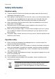
MX945GM2 Electrical safety To prevent electrical shock hazard, disconnect the power cable from the electrical outlet before relocating the system. When adding or removing devices to or from the system, ensure that the power cables for the devices are unplugged before the signal cables are connected. If possible, disconnect all power cables from the existing system before you add a device. Before connecting or removing signal cables from the motherboard, ensure that all power cables are unplugged.
User’s Manual If a problem arises with your system and no solution can be obtained from the user’s manual, please contact your place of purchase or local distributor. Alternatively, please try the following help resources for further guidance. Visit the Advansus website for FAQ, technical guide, BIOS updates, driver updates, and other information: http://www.advansus.com.tw/Support/Support.
MX945GM2 ! " #$ Before you begin installing your single board, please make sure that the following materials have been shipped: 1 x i945GME Mini ITX Main board 1 x CD-ROM contains the followings: User’s manual (this manual in PDF file) Drivers 2 x COM cable 1 x IDE HDD cable (40-pin, pitch 2.54mm) 2 x SATA cable kit (SATA/Power) 1 x Startup Manual If any of the above items is damaged or missing, please contact your retailer.
User’s Manual % & Revision V 1.0 Revision History First release for PCB 1.
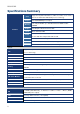
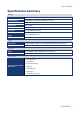
MX945GM2 CPU Chipset Memory Features Graphic Panel Audio LAN Supports Intel µFC-PGA 478 Core 2 Duo / Core Duo / Core 2 Solo / Core Solo mobile CPU with 65nm process technology Intel 82945GME Express Chipset Two 240-pin DIMMs up to 4GB Dual Channel DDR2 533/667 SDRAM Intel Graphics Media Accelerator 950 Dual 18/24*-bit LVDS Realtek ALC888 Audio Code 5.1 CH.
User’s Manual Display Chipset Intel® 82945GME GMCH integrated Graphics Media Accelerator 950 Display Memory Intel® DVMT 3.0 supports 224 MB video memory Resolution 2048 x 1536 @ 32 bpp (85 Hz) Dual Display CRT + LVDS LVDS Intel® 945GME Dual 18-bit/24-bit LVDS 2nd LVDS Through ADD2 LVDS Card DVI / Onboard DVI Chips Secondary VGA Through ADD2 DVI Card Through ADD2 VGA Card Audio AC97 Codec Realtek ALC888 supports 5.1-CH with two independent audio stream Audio Interface Mic.
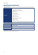
MX945GM2 Internal I/O Connector 2 x USB connectors support additional 4 USB ports 1 x 20-pin ATX Power connector 1 x 40-pin IDE connector for two devices 3 x COM connector 2 x SATA connectors Internal I/O 1 x System panel connector 1 x CD-In connector 1 x SPDIF out connector 1 x SMbus management connector 1 x LVDS connector 1 x CPU Fan connector 2 x 6pin connector support 8Bit GPIO via SMbus PCA9554 Controller (Optional) Mechanical & Environmental Power Type ATX Operating Temperature 0~60°C (32~140°F)
User’s Manual ' "( # MX945GM2 11
MX945GM2 This chapter describes the main board features and the new technologies it supports.
User’s Manual ! 1.1 Before you Proceed Take note of the following precautions before you install motherboard components or change any motherboard settings. Unplug the power cord from the wall socket before touching any component. Use a grounded wrist strap or touch a safely grounded object or a metal object, such as the power supply case, before handling components to avoid damaging them due to static electricity Hold components by the edges to avoid touching the ICs on them.
MX945GM2 1.2 Motherboard Overview Before you install the motherboard, study the configuration of your chassis to ensure that the motherboard fits into it. Refer to the chassis documentation before installing the motherboard. Make sure to unplug the power cord before installing or removing the motherboard. Failure to do so can cause you physical injury and damage motherboard components. 1.2.
User’s Manual 1.
MX945GM2 1.3.1 Layout Content List Slots Label Function Note (Rear side) Page CF1 Compact Flash Connector N/A DIMM1 240-pin DDR2 DIMM slot N/A DIMM2 240-pin DDR2 DIMM slot N/A MINI_PCI1 Mini PCI Slot N/A PCIEX16 PCI Express X16 Slot N/A PCI1 PCI Slot N/A Jumpers Label Function Note Page J4 Clear CMOS 3 x 1 header, pitch 2.00mm 30 J6 Watchdog Timer Output Select 3 x 1 header, pitch 2.00mm 31 J7 AT/ATX Power Select 3 x 1 header, pitch 2.
User’s Manual Internal Connector Label Function Note Page ATX_PWR1 ATX Power Connector 10 x 2 header 35 CN4 USB 2.0 Connector 5 x 2 header, pitch 2.00mm 36 CN5 USB 2.0 Connector 5 x 2 header, pitch 2.00mm 36 CN6 Serial Port 2 Connector 5 x 2 header, pitch 2.00mm 37 CN7 Serial Port 3 Connector 5 x 2 header, pitch 2.00mm 37 CN8 Serial Port 4 Connector 5 x 2 header, pitch 2.00mm 38 CN16 Front Panel Audio Connector 5 x 2 header, pitch 2.
MX945GM2 1.4 Central Processing Unit (CPU) The motherboard comes with a surface mount 478-pin socket designed for the Intel® Core 2 Duo / Core Duo / Core 2 Solo / Core Solo CPU with 65nm process. Take one of the marked corner (with gold triangle) on the CPU. This mark should match a specific corner on the socket to ensure correct installation. Make sure the AC power is off before you install the CPU.
User’s Manual 1.4.1 Installing the CPU 1. Locate the CPU socket on the motherboard. Before installing the CPU, make sure that the socket box is facing towards you. 2. The processor socket comes with a screw to secure the processor, please unlock the screw first.
MX945GM2 3. Position the CPU above the socket and the gold triangular mark on the CPU must align with pin 1 of the CPU socket. 4. 5. Carefully insert the CPU into the socket until it fits in place ‘Gold mark’. Turn the screw to the lock position. The CPU fits in only one correct orientation. DO NOT force the CPU into the socket to prevent bending the connectors on the socket and damaging the CPU. After installation, make sure to plug-in the ATX power cable to the motherboard.
User’s Manual 1.4.2 Installing the CPU Heatsink and Fan The Intel® socket 478P Core Duo / Core Solo / Core 2 Duo CPU processor requires a specially designed heatsink and fan assembly to ensure optimum thermal condition and performance. Install the motherboard to the chassis before you install the CPU fan and heatsink assembly. When you buy a boxed Intel® processor, the package includes the CPU fan and heatsink assembly.
MX945GM2 2. Push down two fasteners at a time in a diagonal sequence to secure the heatsink and fan assembly in place. 3. Connect the CPU fan cable to the connector on the motherboard labelled C_FAN1. Do not forget to connect the fan cables to the fan connectors. Insufficient air flow inside the system may damage the motherboard components, and hardware monitoring errors can occur if you fail to plug this connector. These are not jumpers! DO NOT place jumper caps on the fan connectors.
User’s Manual 1.4.3 Uninstalling the CPU Heatsink and Fan 1. Disconnect the CPU fan cable from the connector on the motherboard. 2. Rotate each fastener counterclockwise. 3. Pull up two fasteners at a time in a diagonal sequence to disengage the heatsink and fan assembly from the motherboard 4. Carefully remove the heatsink and fan assembly from the motherboard. Refer to the documentation in the boxed or stand-alone CPU fan package for detailed information on CPU fan installation.
MX945GM2 1.5 System Memory 1.5.1 DIMM Sockets Location The motherboard comes with four 240-pin Double Data Rate 2 (DDR2) Dual Inline Memory Modules (DIMM) sockets. A DDR2 module has the same physical dimensions as a DDR DIMM but has a 240-pin footprint compared to the 184-pin DDR DIMM. DDR2 DIMMs are notched differently to prevent installation on a DDR DIMM socket.
User’s Manual 1.5.2 Memory Configurations You can install 128 MB, 256 MB, 512 MB, 1GB and 2GB DDR2 SDRAM DIMMs into the SODIMM sockets using the memory configurations in this section. Installing DDR2 DIMM other than the recommended configurations may cause memory sizing error or system boot failure. Use any of the recommended configurations. For dual-channel configuration, the total size of memory module(s) installed per channel must be the same (DIMM1 = DIMM2).
MX945GM2 1.5.3 Installing a DDR2 DIMM Make sure to unplug the power supply before adding or removing DIMMs or other system components. Failure to do so may cause severe damage to both the motherboard and the components. 1. 2. 3. Unlock a DIMM socket by pressing the retaining clips outward Align a DIMM on the socket such that the notch on the DIMM matches the break on the socket. Firmly insert the DIMM into the socket until the retaining clips snap back in place and the DIMM.
User’s Manual 1.6 Expansion Slots In the future, you may need to install expansion cards. The following sub sections describe the slots and the expansion cards that they support. Make sure to unplug the power cord before adding or removing expansion cards. Failure to do so may cause you physical injury and damage motherboard components. 1.6.1 Installing an Expansion Card 1. Before installing the expansion card, read the documentation that came with it and make the necessary hardware settings for the card.
MX945GM2 1.6.
User’s Manual 1.6.4 PCI Slots MX945GM2 has one PCI slots. The PCI slots support cards such as a LAN card, SCSI card, USB card, and other cards that comply with PCI specifications. The figure shows a LAN card installed on a PCI slot. 1.6.5 PCI Express X16 Slot This motherboard supports one PCI Express x16 graphic cards that comply with the PCI Express specifications. The following figure shows a graphics card installed on the PCI Express x16 slot. 1.6.
MX945GM2 1.7 Jumpers 1.7.1 Clear CMOS (J4) This jumper allows you to clear the Real Time Clock (RTC) RAM in CMOS. You can clear the CMOS memory of date, time, and system setup parameters by erasing the CMOS RTC RAM data. The onboard button cell battery powers the RAM data in CMOS, which include system setup information such as system passwords. To erase the RTC RAM: 1. 2. 3. Turn OFF the computer and unplug the power cord. Remove the onboard battery.
User’s Manual 1.7.2 Watchdog Timer Output Select (J6) Enable Disable 1.7.
MX945GM2 1.7.4 LVDS Extended Setting (J14) Enable * Disable 1.7.
User’s Manual 1.8 Connectors 1.8.1 Rear Panel Connectors No 1 Label CN10 Function PS/2 mouse connector 2 3, 4 CN1 CN3, CN2 Serial port connector LAN (RJ-45) connector Description The standard PS/2 mouse DIN connector is for a PS/2 mouse. D-sub 9-pin, male This port allows Gigabit connection to a Local Area Network (LAN) through a network hub. Refer to the table below for the LAN port LED indications.
MX945GM2 No 5 Label AUDIO1 Function Line-In port (Light Blue). 6 AUDIO1 Line-Out port (Lime) 7 8 AUDIO1 CN2 Microphone port (Pink) USB 2.0 connector 9 CN3 USB 2.0 connector 10 CN1 VGA port 11 CN10 PS/2 KB connector 34 Description This port connects a tape, CD, DVD player, or other audio sources. This port connects a headphone or a speaker. In 4-channel, 6-channel, and 8-channel configuration, the function of this port becomes Front Speaker Out. This port connects a microphone.
User’s Manual 1.8.2 ATX Power Connector (ATX_PWR1) This connector is for an ATX Micro-Fit power supply. The plugs from the power supply are designed to fit these connectors in only one orientation. Find the proper orientation and push down firmly until the connectors completely fit. Important notes on the Motherboard Power Requirements Make sure that your ATX 12V power supply can provide 8A on the +12V lead and at least 1A on the +5-volt standby lead (+5VSB).
MX945GM2 1.8.3 USB 2.0 Connector (CN4, CN5) These connectors are for USB 2.0 ports. Connect the USB/GAME module cable to any of these connectors, then install the module to a slot opening at the back of the system chassis. These USB connectors comply with USB 2.0 specification that supports up to 480 Mbps connection speed. CN4 CN5 CN5 CN4 Never connect a 1394 cable to the USB connectors. Doing so will damage the motherboard! The USB module is purchased separately.
User’s Manual 1.8.4 Serial Port 2 Connector (CN6) 1.8.
MX945GM2 1.8.6 Serial Port 4 Connector (CN8) 1.8.7 Front Panel Audio Connector (CN16) This connector is for a chassis-mounted front panel audio I/O module that supports either HD Audio or legacy AC ‘97 (optional) audio standard. Connect one end of the front panel audio I/O module cable to this connector.
User’s Manual 1.8.8 Case Open and Speaker Out Connector (CN19) 1.8.9 CPU Fan Connector (C_FAN1) Do not forget to connect the fan cables to the fan connectors. Insufficient air flow inside the system may damage the motherboard components, and hardware monitoring errors can occur if you fail to plug this connector. These are not jumpers! DO NOT place jumper caps on the fan connectors.
MX945GM2 1.8.10 System Panel Connector (F_PANEL1) This connector supports several chassis-mounted functions. System Power LED (2-pin PWRLED) This 2-pin connector is for the system power LED. Connect the chassis power LED cable to this connector. The system power LED lights up when you turn on the system power, and blinks when the system is in sleep mode. ATX Power Button/Soft-off Button (2-pin PWRSW) This connector is for the system power button.
User’s Manual 1.8.11 Primary IDE Connector (IDE1) Orient the red markings (usually zigzag) on the IDE cable to Pin 1. 1.8.
MX945GM2 1.8.13 Amplifier Connector (JAMP1) 1.8.14 Optical Drive Audio Connector (JCD1) This connector is for the 4-pin audio cable that connects to the audio connector at the back of the optical drive Enable the CD-IN function in the audio utility when using this connector.
User’s Manual 1.8.15 LCD Inverter Connector (JBKL1) Signal Description Signal VR Signal Description For inverter with adjustable Backlight function, it is possible to control the LCD brightness through the VR signal. Vadj=0.75V ~ 4.25V (Recommended: 4.
MX945GM2 1.8.16 Digital I/O Connector (JGPIO1) 1.8.
User’s Manual 1.8.18 LVDS Connector (JLVDS1) 1.8.19 Serial ATA Connector [Black] (SA1, SA2) SA1 SA2 SA2 SA1 Install the Windows® 2000 Service Pack 4 or the Windows® XP Service Pack1 before using Serial ATA. When using the connectors in Standard IDE mode, connect the primary (boot) hard disk drive to the SATA1 connector.
MX945GM2 1.8.20 SM Bus Connector (SM_BUS1) 1.8.21 Digital Audio Connector (SPDIF_OUT1) This connector is for an additional Sony/Philips Digital Interface (S/PDIF) port(s). Connect the S/PDIF module cable to this connector, then install the module to a slot opening at the back of the system chassis. The S/PDIF module is purchased separately.
User’s Manual 1.8.