Intel® NetStructure™ MPRTM4808 Rear Transition Board Installation Guide December 2004 Order Number: 301370-002
INFORMATION IN THIS DOCUMENT IS PROVIDED IN CONNECTION WITH INTELR PRODUCTS. EXCEPT AS PROVIDED IN INTEL’S TERMS AND CONDITIONS OF SALE FOR SUCH PRODUCTS, INTEL ASSUMES NO LIABILITY WHATSOEVER, AND INTEL DISCLAIMS ANY EXPRESS OR IMPLIED WARRANTY RELATING TO SALE AND/OR USE OF INTEL PRODUCTS, INCLUDING LIABILITY OR WARRANTIES RELATING TO FITNESS FOR A PARTICULAR PURPOSE, MERCHANTABILITY, OR INFRINGEMENT OF ANY PATENT, COPYRIGHT, OR OTHER INTELLECTUAL PROPERTY RIGHT.
Contents Contents 1 Using This Guide ............................................................................................................................. 6 1.1 1.2 2 Operating Safety.............................................................................................................................. 7 2.1 2.2 2.3 2.4 2.5 2.6 2.7 3 Electromagnetic Compatibility (EMC) ................................................................................... 7 Switch Settings ..................
Contents 5 Warranty Information ..................................................................................................................... 30 5.1 6 Intel® NetStructure™ Compute Boards & Platform Products Limited Warranty................. 30 5.1.1 Returning a Defective Product (RMA) ................................................................... 30 Customer Support .........................................................................................................................
Contents Revision History Date Revision Description May 2004 001 Initial release of this manual December 2004 002 Modified Serial Connectors information Intel® NetStructure™ MPRTM4808 Rear Transition Board Installation Guide 5
Using This Guide 1 Using This Guide The Intel® NetStructure™ MPRTM4808 Rear Transition Board Installation Guide is intended for users qualified in electronics or electrical engineering. Users should have a working understanding of PCI, CompactCPCI, and telecommunications. 1.1 Terms and Definitions Table 1. Terms and Definitions Abbreviation 1.
Operating Safety Operating Safety 2 This section provides safety precautions to follow when installing, operating, and maintaining the Intel® NetStructure™ MPRTM4808 Rear Transition Board. Intel intends to provide all necessary information to install and handle the Intel MPRTM4808 board in this Installation Guide. However, as the product is complex and its usage manifold, Intel does not guarantee that the given information is complete. For additional information, contact your Intel representative.
Operating Safety 2.3 Installation Electrostatic discharge and incorrect board installation and removal can damage circuits or shorten their life. Therefore: • Make sure that you are working in an ESD-safe environment before touching boards or electronic components. • When plugging in or removing the board, do not press or pull on the front panel; use the handles. • Before installing or removing an additional device or module, read the device’s documentation.
Operating Safety 2.6 RJ-45 Connector The Intel MPRTM4808 board provides several RJ-45 connectors that commonly serve as different interfaces (RS-485, twisted-pair Ethernet, and telephone). Connecting different interfaces (e.g., Ethernet and RS-485) may damage the board. Therefore, make sure that you only connect matching interfaces. Furthermore, take note of the following: • Clearly mark TPE connectors near your working area as network connectors.
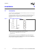
Installation Installation 3.1 3 Introduction The Intel® NetStructure™ MPRTM4808 Rear Transition Board provides easy access to I/O signals of boards via the CompactPCI backplane. Backplane I/O signals are available at connector J5. To connect System Management Bus 1 and the Chassis Management Bus to the board, the Intel MPRTM4808 board provides the Intelligent Platform Management Bus 1 (IPMB1) and Intelligent Chassis Management Bus (ICMB) connectors. Figure 1.
Installation 3.2 Standard Compliances The Intel MPRTM4808 board meets the following standards: Table 2. Standard Compliances Standard 3.3 Description EN 60950 UL/cUL 1950 Legal safety requirements EN 55022 EN 55024 EN 61000-6-2 FCC Part 15 Class A EMC requirements on system level ANSI/IPC-A-610 Rev.C Class 2 ANSI/IPC-7711 ANSI/IPC-7721 ANSI-J-001...003 Manufacturing standards On-Board Connectors The Intel MPRTM4808 board provides the following on-board connectors: Figure 2.
Installation 3.3.1 Secondary EIDE Interface The Intel MPRTM4808 board provides the secondary EIDE interface via CompactPCI connector J5. The secondary EIDE interface can be used for: • One EIDE device • Two EIDE devices • One EIDE device and one CompactFlash disk Caution: • If more than two IDE devices are connected to the IDE bus, the bus is unable to recognize all of the devices, and the baseboard might not start correctly.
Installation Figure 4. Note: 3.3.1.3 Note: Location of CompactFlash Slot CompactFlash disks of types I and II are supported. Installation Procedure To configure the card to the supported true-IDE mode, the card must already be inserted when the board’s power is turned on. Inserting the CompactFlash while the board’s power is still on will configure the CompactFlash disk to PC Card ATA mode, which is not supported by the CPU board.
Installation 3.3.1.4 Removal Procedure 1. Turn off CPU power. 2. Press ejector pin. The ejector pin loosens the CompactFlash disk from the socket. 3. Remove CompactFlash disk from Intel MPRTM4808 board. 4. Turn on CPU power. 3.3.2 Floppy Disk Drive Note: The board is not hot-swappable if a floppy disk drive is connected to the Intel MPRTM4808 board. The floppy disk drive connector is a 34-pin 2.54-mm pin-pitch connector. The following connector pinout shows how the pins are assigned. Figure 6.
Installation 3.3.4 PMC I/O Signals The I/O signals of PMC Slots 1 and 2 of the CPU board are routed to two 64-pin connectors. Figure 8 and Figure 9 show the pinouts. Figure 8.
Installation Figure 9.
Installation 3.4 Caution: Switch Settings The Intel MPRTM4808 board provides two on-board switches and one FP reset switch. The switches must be set to OFF to avoid damage to attached PMC modules. Figure 10. Location of Switches Table 3. Switch Settings Switch SW2 No. 1 2 SW3 1 2 3.
Installation • Before touching integrated circuits, make sure that you are working in an ESD-safe environment. • When plugging the board in or removing it, use the handles; do not press on the front panel. 3.5.1 Installation Procedure Note: Connect interface cables to the on-board connectors first, since it may be difficult to reach them when the Intel MPRTM4808 board is already installed into the CompactPCI backplane.
Installation 3.5.2 Removal Procedure 1. Check all installed boards for steps to perform before turning off power. 2. Turn off system power. 3. Unfasten screws of front panel until Intel MPRTM4808 board is detached from rack frame. 4. Unlock handles by pressing on red handle buttons. 5. Press handles outward to disconnect the Intel MPRTM4808 board from backplane. 6. Carefully remove Intel MPRTM4808 board from slot, making sure not to bend any pins. 7. Turn on system power. 3.
Installation Figure 13. J3 Connector Pinout (Rows D and E) Figure 14.
Installation Figure 15.
Installation 3.7 Front Panel Connectors and Controls The Intel MPRTM4808 board front panel provides the following connectors and controls: Figure 16. Caution: Front Panel Connectors and Controls The Intel MPRTM4808 board provides several RJ-45 connectors that commonly serve as different interfaces (RS-485, twisted pair Ethernet and telephone). Connecting different interfaces (e.g. Ethernet and RS-485) may damage the board. Therefore, make sure that you only connect matching interfaces.
Installation 3.7.1 ICMB Connector The ICMB connector can be used to attach the Intel NetStructure MPCBL5525 System Master Board via the Intel MPRTM4808 board to other systems based on the IPMI. To monitor the overall system, the chassis can be connected via the Intel MPRTM4808 boards. The IPMI signals are routed from the CPU via the backplane to the Intel MPRTM4808 board and are then available on the ICMB connector. The ICMB bus must be connected via a multi-drop cable or star topology.
Installation 3.7.3 Serial Connectors Two serial devices can be connected via the two COM connectors, and one USB device (e.g., USB keyboard, USB mouse) can be connected via the USB connector. Note: The two COM ports are only available if the Intel MPRTM4808 board is used together with the Intel NetStructure MPCBL5525 System Master Board. Figure 19 shows how the USB connector pins are assigned. Figure 19. USB Connector Pinout COM connector pins are assigned as shown below. Figure 20.
Installation The translation between the DB-9 and RJ-45 connectors is llustrated in the following diagram: Figure 21. DB9 to RJ-45 Translation Male RJ-45 connector Pin Pin Female DB-9 connector 3.7.4 Reset Key The Intel MPRTM4808 board provides a reset key on the front panel to execute a reset on the Intel NetStructure MPCBL5525 System Master Board in systems where the back can be accessed more easily than the front.
Agency Approvals Agency Approvals 4.1 4 CE Certification The Intel® NetStructure™ MPRTM4808 Rear Transition Board meets intent of Directive 89/336/ EEC for Electromagnetic Compatibility and Low-Voltage Directive 73/23/EEC for Product Safety. The Intel MPRTM4808 board has been designed for NEBS/ETSI compliance. 4.2 Safety Certifications UL/cUL 60950 Safety for Information Technology Equipment (UL File # E179737) 4.
Agency Approvals 4.3.2 EN 55024 Immunity GR-1089-CORE Sections 2 and 3 EN 61000 4-2 Electro-Static Discharge (ESD) EN 61000 4-3 Radiated Susceptibility EN 61000 4-4 Electrical Fast Transient Burst EN 61000 4-5 Power Line Surge EN 61000 4-6 Frequency Magnetic Fields EN 61000 4-11 Voltage dips, Variations, and Short Interruptions 4.4 Regulatory Information 4.4.
Agency Approvals 4.5 Product Safety Information 4.5.1 Safety Precautions Review the following precautions to avoid injury and prevent damage to this product, or any products to which it is connected. To avoid potential hazards, use the product only as specified. Read all safety information provided in the component product user manuals and understand the precautions associated with safety symbols, written warnings, and cautions before accessing parts or locations within the unit.
Agency Approvals 4.6 AC and/or DC Power Safety Warning (AC and/or DC Powered Units) The AC and/or DC power cord is your unit's main AC and/or DC disconnecting device, and must be easily accessible at all times. Auxiliary AC and/or DC On/Off switches and/or circuit breaker switches are for power control functions only (NOT THE MAIN DISCONNECT). For your safety, use only a power cord with a grounded plug. The enclosure is also provided with a separate earth ground connection/stud.
Warranty Information Warranty Information 5.
Warranty Information 5.1.1.1 For the Americas Return Material Authorization (RMA) credit requests e-mail address: requests.rma@intel.com Direct Return Authorization (DRA) repair requests e-mail address: uspss.repair@intel.com DRA on-line form: http://support.intel.com/support/motherboards/draform.htm Intel Business Link (IBL): www.intel.com/ibl Telephone No.: 1-800-INTEL4U or 480-554-4904 Office Hours: Monday - Friday 0700-1700 MST Winter / PST Summer 5.1.1.
Warranty Information If the Customer Support Group verifies that the product is defective, they will have the Direct Return Authorization/Return Material Authorization Department issue you a DRA/RMA number to place on the outer package of the product. Intel cannot accept any product without a DRA/RMA number on the package.
Customer Support Customer Support 6 This section offers technical and sales assistance information for this product, and information on returning an Intel® NetStructure™ product for service. 6.1 Technical Support and Return for Service Assistance For all product returns and support issues, please contact your Intel product distributor or Intel sales representative for specific information. 6.