Intel NetStructure® MPRTM0020 Rear Transition Module Technical Product Specification April 2006 Order Number: 309383-004
INFORMATION IN THIS DOCUMENT IS PROVIDED IN CONNECTION WITH INTEL® PRODUCTS. NO LICENSE, EXPRESS OR IMPLIED, BY ESTOPPEL OR OTHERWISE, TO ANY INTELLECTUAL PROPERTY RIGHTS IS GRANTED BY THIS DOCUMENT.
Contents 1 Document Organization ................................................................................................................ 7 1.1 Acronyms and Terms............................................................................................................ 7 2 Functional Overview ..................................................................................................................... 9 3 Operating the Unit ..............................................................
6.4.1 6.5 7 Mean Time Between Failure (MTBF) Specifications ............................................. 35 6.4.1.1 Environmental Assumptions .................................................................. 35 6.4.1.2 General Assumptions............................................................................. 35 6.4.1.3 General Notes........................................................................................ 36 Power Consumption ..........................................................
Tables 1 2 3 4 5 6 7 8 9 10 11 12 13 14 15 16 17 18 19 Acronyms and Terms.................................................................................................................... 7 Serial Port Connector Pinout ...................................................................................................... 18 USB Connector Pinout................................................................................................................ 18 RJ-45 Ethernet Connector Pinout.................
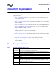
Revision History Date Revision April 2006 004 Description Updated values for temperature sensor thresholds in “Sensor Data Record for RTM” table. Updated faceplate illustration. Initial production release. 6 January 2006 003 December 2005 002 Added “Operating the Unit”, “RTM Management Architecture”, and “Detailed Specifications” chapters September 2005 001 Initial release of this document. Added new info on grounding procedure, power supplies, SAS redriver, faceplate LEDs, and RTM sensors.
Document Organization 1 Document Organization The Intel NetStructure® MPRTM0020 Rear Transition Module Technical Product Specification is organized as follows: • Chapter 1, “Document Organization” provides a table of acronyms and terms that are used throughout the document. • Chapter 2, “Functional Overview” describes the features of the Rear Transition Module. • Chapter 3, “Operating the Unit” includes information about installing and removing the Rear Transition Module.
Document Organization Table 1. Acronyms and Terms (Sheet 2 of 2) Term 8 Definition Hot Swap A specific specification from the PICMG 3.0 Spec. I2 C A two-wire serial bus. Licensed by Phillips Semiconductors. IA-32 32-bit Intel® Architecture I/O Input/Output IPMB Intelligent Platform Management Bus. The bus that interconnects all boards in the chassis to the Shelf Manager. IPMB-0 Intelligent Platform Management Bus Channel 0 as defined in the IPMI v1.5 specification.
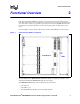
Functional Overview 2 Functional Overview Rear Transition Modules (RTM) are important components in many telecommunications and embedded systems. These environments place most of the active components on a Front Board and most of the cable connections (especially copper cables) are made from the RTM. This allows the Front Board to be replaced without the need to reinsert a large number of cables in the correct order.
Functional Overview • One SAS x4 connector to support external SAS JBOD. (Only three of these SAS ports on the RTM are usable; the first SAS port is used by the MPCBL0020 Single Board Computer’s local SAS drive.) • Six T1/E1 ports with transformer and protection circuitry (designed primarily for intrabuilding applications) • I2C connectivity to the SBC for remote management capabilities • OOS and Health LEDs • Hot Swap status LED.
Operating the Unit Operating the Unit 3.1 3 Introduction The Intel NetStructure® MPRTM0020 Rear Transition Module is a non-intelligent RTM. A nonintelligent FRU does not have a remote management controller (RMC) on board to communicate with the SBC IPMC. Instead, all of the non-intelligent RTM sensors and FRU device information is made available to the IPMC through direct device access. This is usually done via dummy I2C sensor and storage devices.
Operating the Unit 3.4 Digital Ground to Chassis Ground Connection Digital ground can be tied to chassis ground through a jumper (P2) located near the bottom, right corner of the RTM. In the default grounding for the MPRTM0020, digital ground is isolated from chassis ground (jumper link connecting “NC” to “GND”) as shown in Figure 2. Figure 2. Default Grounding on MPRTM0020 To connect the digital ground to the chassis ground, follow this procedure: 1.
Operating the Unit Figure 3. Note: Digital Ground Connected to Chassis Ground Digital ground is also called “logic ground”. Chassis ground is also known as “shelf ground”.
Module Components 4 Module Components 4.1 Block Diagram Figure 4 shows a functional block diagram of the RTM. Figure 4. RTM Functional Block Diagram P30 Power IPMB/I2C P31 ADM1026 RMD Redriver P32 SAS (x3) 3 SAS Port 2xGbE (from Fabric Interface) USB RJ-45 GbE Port RJ-45 GbE Port USB Port P33 Serial RJ-45 Serial Port From Mezz. #1 2xT1/E1 From Mezz. #2 2xT1/E1 Transformers / Sidactors Backplane 2xT1/E1 1x6 RJ-48C T1/E1 Ports From Mezz.
Module Components 4.2 Physical Layout Figure 5.
Module Components Figure 6 identifies the connectors and LEDs on the RTM faceplate. Figure 6.
Module Components 4.3 Components Description The following sections describe the components shown in Figure 4 through Figure 6. 4.3.1 Serial Port Interface One serial port (RS-232) connector is present on the RTM. This connector provides access to the COM1 serial port from the MPCBL0020 Single Board Computer, which is also routed to the front panel of the SBC. Both connections are active, but only one can be used at any given time. The line driver/receiver for the serial port resides on the SBC.
Module Components Table 2. Serial Port Connector Pinout Pin 4.3.2 Signal Name 1 RTS 2 DTR 3 TXD 4 GND 5 GND 6 RXD 7 DSR 8 CTS USB Interface One USB port is provided on the RTM. 5V power is available through this USB port with a current limit of 400mA. Figure 8 illustrates the USB connector and Table 3 provides pinout information. Figure 8. USB Connector (J2) Table 3. USB Connector Pinout Pin 4.3.
Module Components Figure 9. RJ-45 Gigabit Ethernet Connector Table 4. RJ-45 Ethernet Connector Pinout Pin 4.3.4 Signal Name 1 MDI0+ 2 MDI0– 3 MDI1+ 4 MDI2+ 5 MDI2– 6 MDI1– 7 MDI3+ 8 MDI3– SAS Connector Interface One x4 SAS (Serial Attached SCSI) connector is present on the RTM.
Module Components Figure 10. SAS Connector Pin 2 Pin 23 Pin 25 Pin 24 Table 5. SAS Connector Pinout Pin Note: 4.3.
Module Components Figure 11. RJ-48 Connector Table 6. T1/E1 Connector Pinout Pin 4.3.6 T1 Signal E1 Signal 1 RX_RNG RL1 2 RX_TIP RL2 3 Not Used Not Used 4 TX_RNG XL1 5 TX_TIP XL2 6 Not Used Not Used 7 Not Used Not Used 8 Not Used Not Used Zone 3 Rear Transition Module Power Connector (P30) The P30 connector is a bladed connector originally developed for FutureBus* applications. Figure 12 illustrates the connector outline and Table 7 provides pinout information.
Module Components Figure 12. P30 Connector Table 7. P30 Connector Pinout Pin Table 8. Signal Signal A1 (L) Logic_GND A2 (L) Shelf_GND B1 (L) Logic_GND B2 (L) +3.3V_MP C1 (M) IPMI_Sclk C2 (M) IPMI_Sdata D1 (S +12V D2 (S) +12V E1 (S) PS1# E2 (S) ENABLE# P30 Signal Descriptions Pin 22 Pin Signal Comments A1 Logic_GND Logic ground connection (long contact); provides return path for power and signal connections.
Module Components 4.3.7 Zone 3 Rear Transition Module Data/Control Connectors The MPRTM0020 implementation includes three data connectors (P31, P32, P33) that mate directly to the MPCBL0020 Single Board Computer without connecting through the backplane. Each Zone 3 data/control connection consists of 120-pin HM-Zd connector with 40 differential pairs which allows high-speed signals to be passed between the boards. 4.3.7.
Module Components Table 10. P31 Signal Descriptions (Sheet 2 of 2) Pin Signal Comments A6-F6 LNK[x], ACT[x], SPD1000[x] Represent the link, activity, and speed LEDs for the Fabric Interface Gigabit Ethernet that are routed to the RTM G6, F7 Reserved Reserved G7, H7 PCIe_CLK+, PCIe_CLK- A8-H9 Reserved Reserved A10B10 USB[0]+, USB[0]- USB data signals. Note that the RTM’s 5 V power for the USB connections must be derived off the 12 V rail.
Module Components AP3[x] indicates that these T1/E1 signals are routed from PMC 3. Table 12.
Module Components Table 13. GPIO Signal Mapping (Sheet 2 of 2) GPIO Signals 4.3.10 Pin on ADM1026 Health Red LED Control 9 USB_OC Monitor 12 Payload Power Enable 2 Payload PowerGood 43 Power Supplies The MPRTM0020 RTM needs several voltages that are not available from the SBC. The P30 connection to the SBC only provides two power supplies: • +12 V voltage rail (420 mA maximum current) is used as the main input voltage for the RTM • +3.
Module Components • +1.8V: The 1.8 V voltage is used as the input voltage to the SAS re-driver IC. 4.3.11 SAS Redriver The MPCBL0020 Single Board Computer implements optional SAS storage access via the MPRTM0020 RTM. SAS is a 3-Gbps SERDES style bus, and a redriver is added on the RTM to effectively detect and correct the SAS OOB signals at a proper amplitude. The specific SAS re-driver that was used is the PMC-Sierra* PM8380 Quad SMX 3G SATA/SAS Mux/Demux.
Module Components Table 14. Board Status LED Descriptions LED Hot Swap Function Function: Hot Swap as defined in AdvancedTCA 3.0 Specification It is also possible for a user to override the default behavior of the LED using AdvancedTCA FRU LED Control commands. Possible States: OFF / BLUE / SHORT BLINK / LONG BLINK Blinking Blue: Preparing for removal/insertion.
Module Components The LINK LED has the following indications and meanings: • LED Off – Link not established • Steady green – Link established but not active • Flashing green – Link established and currently active When the LINK LED is illuminated, the SPEED LED has the following indications and meanings: • Steady green – 10/100 Mbps connection • Steady amber – 1000 Mbps connection Note: When the Fabric Interface Gigabit Ethernet links from the MPCBL0020 Single Board Computer are routed to the switch slo
RTM Management Architecture RTM Management Architecture 5.1 5 Introduction This section describes the management support for a non-intelligent Rear Transition Module (RTM) such as the MPRTM0020. A non-intelligent RTM FRU does not have a controller on board to communicate with the SBC IPMC. Instead, all of the non-intelligent RTM sensors and the nonintelligent RTM FRU storage device are connected directly to the SBC IPMC. This is usually done via dummy I2C sensor and storage devices.
RTM Management Architecture 5.4 Power Budget Management The SBC IPMC has inherent knowledge of the non-intelligent RTM power requirements. The IPMC will handle power negotiation commands from the Shelf Manager that are targeted for the non-intelligent RTM FRU ID. By doing this, the Shelf Manager should see the non-intelligent RTM as a separate controller negotiating for a power budget. 5.5 LED Management The SBC IPMC has direct control over the LEDs on the non-intelligent RTM.
RTM Management Architecture • RTM Temp2 • RTM Temp3 • RTM Power Status Table 15. Sensor Data Record for RTM Sensor Name Figure 16. 32 Lower Critical Description Lower Non Critical Upper Non Critical Upper Critical RTM +1.8V For SAS Retimer 1.71 – – 1.89 RTM +3.3V For other Integrated Circuits 3.10 – – 3.47 RTM +3.3V SUS Early voltage for ADM1026 3.11 – – 3.46 RTM +5.0V For USB Interface 4.71 – – 5.23 RTM +5V SUS Early voltage for Hotswap LED 4.73 – – 5.
Detailed Specifications 6 Detailed Specifications 6.1 Dimensions and Weight The weight of the baseboard is 1.14 kg (2.5 lbs.) with packaging materials. 6.2 Environmental Specification The test methodology is a combination of Intel and NEBS test requirements with the intent that the product will pass pure system-level NEBS testing. The following table summarizes environmental limits, both operating and nonoperating. Table 16.
Detailed Specifications Figure 17 below shows the locations of major components of the MPRTM0020. Table 17 lists the components shown in the illustration. Figure 17.
Detailed Specifications Table 17. Board Components Component/Function A SAS Retimer B RMD/ENA jumper. Used to bypass the manageability by the MPCBL0020 SBC IPMC for debugging purposes. Not intended to be use in any field deployment, because changing this default jumper affects the RTM manageability from the ShMC. C ADM1026 D Digital/Chassis Ground Jumper 6.4 Reliability Specifications 6.4.
Detailed Specifications 6.4.1.3 General Notes • Method I, Case I = Based on parts count. Equipment failure is estimated by totaling device failures rates and quantities used. • Quality Level II = Devices purchased to specifications, qualified devices, vendor lot-to-lot controls for AQLs and DPMs. Where available, direct component supplier predictions or actual FIT rates have been used. 6.5 Power Consumption The maximum power consumption of the MPRTM0020 is 5 watts.
Warranty Information Warranty Information 7.
Warranty Information Direct Return Authorization (DRA) repair requests e-mail address: uspss.repair@intel.com DRA on-line form: http://support.intel.com/support/motherboards/draform.htm Intel Business Link (IBL): http://www.intel.com/ibl Telephone No.: 1-800-INTEL4U or 480-554-4904 Office Hours: Monday - Friday 0700-1700 MST Winter / PST Summer 7.2.2 For Europe, Middle East, and Africa (EMEA) Return Material Authorization (RMA) e-mail address EMEA.Returns@Intel.
Warranty Information 7.2.
Customer Support 8 Customer Support 8.1 Customer Support This chapter offers technical and sales assistance information for this product. 8.2 Technical Support and Return for Service Assistance For all product returns and support issues, please contact your Intel product distributor or Intel Sales Representative for specific information. 8.3 Sales Assistance If you have a sales question, please contact your local Intel NetStructure Sales Representative or the Regional Sales Office for your area.
Certifications Certifications 9 Safety: • IEC60950-1 • EN60950 • UL/CSA 60950-1 Hazardous substances: • The Intel NetStructure® MPRTM0020S00Q has been verified to be compliant with the European Directive 2002/95/EC, officially titled “The Restriction on the Use of Hazardous Substances (RoHS) in Electrical and Electronic Equipment” or RoHS. Specifically, this product uses only RoHS compliant parts and Pb-free solder and may take advantage of certain exemptions referenced within the Directive.
Agency Information Agency Information 10.1 10 North America (FCC Class A) Federal Communications Commission (FCC) Part 15 Rules This equipment has been tested and found to comply with the limits for a Class A digital device, pursuant to Part 15 of the FCC Rules. These limits are designed to provide reasonable protection against harmful interference when the equipment is operated in a commercial environment.
Agency Information Compliance with the R&TTE Directive The R&TTE Directive includes its own safety and EMC requirements. Although equipment declared compliant to the R&TTE Directive does not require explicit declaration of conformity to EMC and Low Voltage Directives, above conditions must also be met to satisfy the safety and EMC requirements of the R&TTE Directive.
Safety Warnings Safety Warnings 11.1 11 Safety Precautions Review the following precautions to avoid personal injury and prevent damage to this product or products to which it is connected. To avoid potential hazards, use the product only as specified. Read all safety information and understand the precautions associated with safety symbols, written warnings, and cautions before accessing parts or locations within the unit.