Backup Battery Kit Install Guide: Intel® Storage Controller AXXSCM3S A Guide for Technically Qualified Assemblers of Intel® Identified Subassemblies/ Products Intel Order Number: E13860-003
Disclaimer Information in this document is provided in connection with Intel® products. No license, express or implied, by estoppel or otherwise, to any intellectual property rights is granted by this document.
Safety Information Important Safety Instructions Read all caution and safety statements in this document before performing any of the instructions. See also Intel Server Boards and Server Chassis Safety Information on the Intel® Server Deployment Toolkit CD and/or at http://support.intel.com/support/ motherboards/server/sb/cs-010770.htm. Wichtige Sicherheitshinweise Lesen Sie zunächst sämtliche Warnund Sicherheitshinweise in diesem Dokument, bevor Sie eine der Anweisungen ausführen.
Warnings Heed safety instructions: Before working with your server product, whether you are using this guide or any other resource as a reference, pay close attention to the safety instructions. You must adhere to the assembly instructions in this guide to ensure and maintain compliance with existing product certifications and approvals. Use only the described, regulated components specified in this guide.
Contents Safety Information ..................................................................................................... iii Important Safety Instructions ................................................................................................ iii Wichtige Sicherheitshinweise ............................................................................................... iii Consignes de sécurité ................................................................................................
vi Backup Battery Kit Install Guide: Intel® Storage Controller AXXSCM3S
Backup Battery Kit Install Guide Tools Required • Phillips* screwdriver Kit Contents Backup Battery Kit (MFSCMBBU) Item Quantity Backup Battery 1 Install Guide 1 Backup Battery Kit Installation Instructions Prepare System 1. Read all caution and safety statements listed in this document before performing any of the steps. See the Intel® Server Boards and Server Chassis Safety Information document at http://support.intel.com/support/motherboards/server/sb/cs-010770.
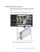
Remove Storage Controller from System 2. Press the retention lever latch button to release the retention lever (see letter “A” in the following figure). Rotate the lever out and away from the module bay (see letter “B”) and pull the storage controller straight out the back of the chassis (see letter “C”). Warning: You must replace the storage controller with a filler panel or another temporary storage controller within two minutes. C A B AF002430 Figure 1.
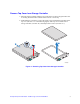
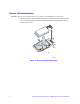
Remove Top Cover from Storage Controller 3. Place the storage controller sideways on a work surface so that it’s largest surface area is touching the work surface and the extraction lever is on the top. 4. With a Phillips* screwdriver, remove the single screw located at the front edge of the top cover (see letter “A” in the following figure). Slide top cover towards rear of storage controller (see letter “B”) and lift upward to remove (see letter “C”). C B A AF002563 Figure 2.
Remove Old Backup Battery Warning: Dispose of used backup battery in accordance with manufacturer’s instructions. 5. Disconnect battery cable from battery connector on the printed circuit board (see letter “A” in the following figure). Remove old backup battery from black plastic battery holder (see letter “B”). B A AF002469 Figure 3.
Install New Backup Battery 6. Install the backup battery in the black plastic battery holder (see letter “A” in the following figure). Connect the battery cable to the battery connector on the printed circuit board (see letter “B”). A B AF002440 Figure 4. Installing New Backup Battery Re-install Top Cover 7. Align notches in top cover with corresponding tabs on storage controller. Slide top cover forward to close. 8. Secure top cover to storage controller with the single screw previously removed.
Install Storage Controller in System 9. Remove filler panel or temporary storage controller if necessary. 10. Ensure the retention lever is out and away from the storage controller (see letter “A” in the following figure). Slide the storage controller into the module bay (see letter “B”) until the bottom of the retention lever engages with the module bay. B A AF002412 Figure 5.