
Datasheet


Intel® Compute Module MFS5000SI TPS 1BProduct Overview
2.2 Compute Module Layout
2.2.1 Connector and Component Locations
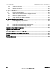
The following figure shows the board layout of the Intel
®
Compute Module MFS5000SI. Each connector
and major component is identified by a number or letter. A description of each identified item is provided
below the figure.
Description Description
A Midplane Power Connector B Midplane Signal Connector
C POST Code Diagnostic LEDs D SAS Controller
E FBDIMM Slots F Intel
®
5000P Memory Controller Hub (MCH)
G CPU #1 Socket H Voltage Regulator Heatsink
I Power/Fault LEDs J Power Button
K Activity and ID LEDs L Video Connector
M USB1 and USB2 Connectors N CPU #2 Socket
O Intel® 6321ESB I/O Controller Hub P CMOS Battery
Q I/O Mezzanine Card Connector
Figure 1. Component and Connector Location Diagram
Revision 1.4 3
Intel order number: E15154-007