Programmer’s Guide MD566X July 2001
MD566X — 56K Data, Fax, and Voice Chipset Revision History Date Revision May 2001 Revise layout. July 2001 Update for V.92 Information in this document is provided in connection with Intel products. No license, express or implied, by estoppel or otherwise, to any intellectual property rights is granted by this document.
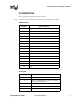
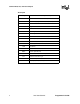
56K V.92 Data, Fax, and Voice Chipset CONVENTIONS This section lists conventions used in this data book. Note: S-registers and AT commands are in bold typeface throughout this document.
56K V.
6K V.92 Data, Fax, and Voice Chipset 1. INTRODUCTION The MD566X Programmer’s Guide describes the software interface of Intel’s V.90/V.92 56K solution. The programmer’s guide includes the AT command sets for data, fax, and voice and the 16C450/16C550A UART emulation. The programmer’s guide should be used with the following Intel publications: the MD566X Datasheet, the IS-101 Voice Application Note, and the Class 1 Fax Application Note. Please note that supported AT commands are firmware revision-dependent.
56K V.92 Data, Fax, and Voice Chipset 1.1 V.92, V.90 and V.34 Data Modes Intel® MD566X chipsets default to the ITU-T V.90 or V.92 data transmission mode depending on the firmware version. The V.90/V.92 mode allows receive data rates of up to 56 kbps over the PSTN (public switched telephone network) only in connections with equipment-compatible ISPs (Internet Service Providers); however, FCC regulations limit receive speeds to 53,333 kbps due to excessive power demands at higher speeds.
56K V.92 Data, Fax, and Voice Chipset Examples of modem responses: OK ERROR CONNECT 28800 0 In the online state, the DCE is off-hook and communicating with a remote modem. Any data sent from the DTE to the DCE is transmitted to the remote modem. Similarly, any data that the DCE receives from the remote modem is transmitted to the DTE. Note: In the online state, the DCE does not ‘echo-back’ any of the data that the DTE sent to the DCE.
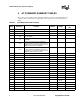
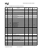
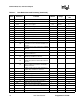
56K V.92 Data, Fax, and Voice Chipset 2. AT COMMAND SUMMARY TABLES This section contains summary tables of all AT commands, S-registers, and manufacturing-only commands. These commands are described fully in the relevant sections of the Programmer’s Guide. Table 2-1. Note ** * Data Mode Command Summary Command Range Reported by &Vn Repeat last command none – no A Answer none – no Bn Select ITU-T or Bell* 1 0–3 yes 1 0, 1 no B0 Selects ITU-T V.22 at 1200 bps and ITU-T V.
56K V.92 Data, Fax, and Voice Chipset Table 2-1.
56K V.92 Data, Fax, and Voice Chipset Table 2-1.
56K V.92 Data, Fax, and Voice Chipset Table 2-1.
56K V.92 Data, Fax, and Voice Chipset Table 2-1.
56K V.
56K V.92 Data, Fax, and Voice Chipset V.44 / V.42 / V.42 bis MNP∗ Command Summary Table 2-2.
56K V.92 Data, Fax, and Voice Chipset V.44 / V.42 / V.42 bis MNP∗ Command Summary (Continued) Table 2-2. Note Command \K2, 3 \K4, 5 * * * * * * \Nn Function Default Range Reported by &Vn Nondestructive/expedited Nondestructive/nonexpedited Set operating mode \N0, \N1 Selects Buffer (Normal) mode with speed buffering \N2 Selects MNP Reliable mode \N3 Selects V.42 Auto-reliable mode \N4 Selects V.
56K V.92 Data, Fax, and Voice Chipset * 16 Value saved in NVRAM.
56K V.92 Data, Fax, and Voice Chipset Table 2-3. Fax Identity Command Summary Command Function Default Range Reported by &Vn +FMDL? Identifies product model none – no +FMFR? Identifies modem manufacturer none – no +FMI? Identifies modem manufacturer none – no +FMM? Identifies product model none – no +FMR? Identifies product version number none – no +FREV? Identifies product version number none – no Range Reported by &Vn Table 2-4.
56K V.92 Data, Fax, and Voice Chipset Table 2-5.
56K V.92 Data, Fax, and Voice Chipset Table 2-7. Response Voice DTE←DCE Character Pairs Hex Code Function 10 Single character in the data stream 1A in data stream 3 End of Record mode data X 58 Packet header for ‘Complex Event Detection Report’ .
56K V.92 Data, Fax, and Voice Chipset Table 2-8.
56K V.92 Data, Fax, and Voice Chipset Table 2-9. Note S-Register Summary (Continued) Register Function * S22 Bit-mapped options * S23 Bit-mapped options * S25 Detect DTR change * S27 Bit-mapped options * S30 * * * Default Range Reported by &Vn – – no none – – no 5 0–255 0.
56K V.92 Data, Fax, and Voice Chipset Table 2-11. V.
56K V.92 Data, Fax, and Voice Chipset Note: The W3 AT command reports the special verbose code listed, which is used to evaluate the modem connection. The W0–W2 AT commands report all other ‘CONNECT’ messages. When the modem is configured for text responses using V1, the W3 verbose response provides information about the DTE data rate, connection modulation, error correction protocol, data compression, and modem-to-modem data rate.
56K V.92 Data, Fax, and Voice Chipset 3. BASIC DATA MODE AT COMMANDS The 56K FastPath chipsets implement: • Standard TIES-compatible AT commands and S-registers in data mode • Standard EIA/TIA-578 AT commands in Class 1 fax mode • Additional AT command sets for error correction, data compression and voice mode In data mode, the AT commands configure the DCE (modem) to establish a connection with a remote data modem. In data mode, the MD566X executes the AT commands for error correction (MNP 2-4, V.
56K V.92 Data, Fax, and Voice Chipset No Echo, Text (E0, V1) AT ATS0? OK 000OK Configure the DCE to use different response codes using the ATWn command (see page 49). The setting for the ATXn command (page 50) can affect which ATWn response codes are reported to the DCE. The ATXn command configures the modem call progress detection and reporting requirements during dialing (for example, dial tone and busy tone detection).
56K V.92 Data, Fax, and Voice Chipset previously-saved telephone numbers can be read from the modem using the view command, AT&Vn. The AT&Zn=x command stores one of four telephone numbers in the NVRAM. To dial these telephone numbers, use the ATDS=n command. If the active profile is not stored in one of the two user profiles after setting up the modem, then the current settings are lost when the commands ATZ or AT&F are issued or when the modem is powered down.
56K V.92 Data, Fax, and Voice Chipset ATI1 Causes the modem to send the modem’s firmware version to the DTE. CD08.55-612 (10/19/99)PARALLEL-SPEAKERPHONE 05-DSP PATCH.001.55 Firmware version that is the modem’s response to the command. 3.5 Establishing a Modem Connection [A, D, DS = n, S0] Data mode provides several methods for establishing a connection with a remote modem. For each modem, a connection can be initiated manually or automatically in both answer and originate modes.
56K V.92 Data, Fax, and Voice Chipset 3.6 Online Command Mode [Escape Codes, On] After establishing a connection with a remote modem, the DTE sends the appropriate escape sequence to the DCE, which causes the DCE to enter the online command mode. The online command mode is used to send AT commands to the DCE while the DCE is still connected to the remote modem. The supported escape sequences are described in Section 3.10. To re-enter the online data mode, use the ATOn command.
56K V.92 Data, Fax, and Voice Chipset The V.92 Quick Connect feature is controlled by the +PSS and +PQC commands. The +PQC command enables and disables the shorten phase 1 and or phase 2 startup procedures. The +PSS command forces either a short or full startup procedure on the next and subsequent connections. To enable the modem for V.92 Quick Connect, set +PSS=0 or 1 and +PQC=0. Refer to Table 3-4. for the detailed description of these commands.
56K V.92 Data, Fax, and Voice Chipset allows the DTE-to-modem data rate to be different from the modem-to-modem data rate. Users can take advantage of this feature by setting the DTE-to-modem rate to a high speed like 115,200 bps and letting the modem negotiate the best line rate. The MD566X chipsets can be configured (by the +MS=m command) to support either asymmetrical or symmetrical connections.
56K V.
56K V.
56K V.92 Data, Fax, and Voice Chipset To configure the DTE-to-modem data rate (in data on-hook command mode), change the terminal program COM port speed selection or write the appropriate divisor latch values for a given speed to the UART Divisor Latch registers. Then send an AT or any other valid AT command to the modem. The modem responds with an OK at the new data rate. All commands and modem responses that follow use the new data rate.
56K V.92 Data, Fax, and Voice Chipset The allowable connection modulations and data rates are determined by the +MS=m command, which uses four parameters: , , , and . The +MS=m parameter defines the top modulation rate.
56K V.92 Data, Fax, and Voice Chipset S-register S37 specifies the maximum data rate that can be attempted during a modem connection. If S37 is set to ‘0’, then the modem looks at the DTE rate to determine the maximum connection data rate. If the DTE data rate doesn’t match one of the data rates, then the modem uses the next-fastest data rate. The +MS command sets the modulation speeds in the MD566X chipsets; however, to set the modulation to either V.
56K V.92 Data, Fax, and Voice Chipset 3.9 Diagnostic Testing [S18, &Tn] The &Tn command initiates loopback tests. Setting S-register S18 to a non-zero value determines the length of testing after the modem receives the &Tn command. After the testing period elapses, the modem halts the test and returns to command mode. To abort the test before the test timer has timed out, enter the escape code sequence followed by AT&T0. Setting S18 to an ’0’ disables the test timer.
56K V.92 Data, Fax, and Voice Chipset the same as the test string, then the DTE-to-modem communication channel is working properly. +++AT TIES Escape Sequence is used to return to command mode. OK Modem enters command mode. AT&T0 Terminates any loopback test. OK Modem aborts analog loopback and stays in command mode.
56K V.92 Data, Fax, and Voice Chipset 3.9.2 Local Analog Loopback With Self-Test [AT&T8] This test is used by the local DTE to check the DTE-to-modem communication integrity. LOCAL MODEM TXD PATTERN GENERATOR TRANSMITTER PATTERN CHECKER RECEIVER DTE RXD Figure 3-3. Local Analog Loopback with Self-Test Local Modem (or Test Modem) AT&F &W Returns the modem to the factory defaults. AT S18=20 &T8 Causes the modem to start local analog loopback with self-test for 20 seconds.
56K V.92 Data, Fax, and Voice Chipset OK command mode. 3.10 AT Escape Sequences The 56K family provides the industry-standard Time Independent Escape Sequence (TIES). The DTE sends the escape sequence to return the modem to command state while in the online data state (that is, connected to another modem) or in diagnostic mode (&Tn commands). Intel also makes the Hayes∗ Escape Sequence available to customers; however, see the following statement regarding licensing requirements.
56K V.92 Data, Fax, and Voice Chipset command mode and sends an ‘OK’ message. After sending the “OK” message, the modem echoes any received data from the DTE while in command mode. 2) An “A” or “a” is received from the DTE. The modem disables the EPD timer and sends the character to the remote modem. The modem then stores any received data from the DTE into the modem internal command buffer and sends the data to the remote modem.
56K V.92 Data, Fax, and Voice Chipset The escape character is determined by the value stored in S-register S2, and it is typically a ‘+’ character. The following is an example of the TIES Escape Sequence: Format: char1 = char2 = char3 = escape character (S2) Example: Note: Table 3-4. Note: Command DTE: +++ AT DCE: OK TIES requires that the three-character escape sequence be contiguous and not repeated.
56K V.92 Data, Fax, and Voice Chipset Table 3-4. Data Mode Command Descriptions (Continued) Select ITU-T or Bell∗: This command selects the ITU-T or Bell configuration for the modem. Bn Cn 42 n=0 Selects ITU-T V.22 when the modem is at 1200 bps and ITU-T V.21 when the modem is at 300 bps. n = 1** Selects Bell 212A when the modem is at 1200 bps and Bell 103J when the modem is at 300 bps. n=2 Selects ITU-T V.
56K V.92 Data, Fax, and Voice Chipset Table 3-4. Data Mode Command Descriptions (Continued) Dial Command: This command causes the modem to immediately go offhook as an originating modem and dial a telephone number with corresponding dial modifiers. Dial modifiers are parameters that define how the modem should dial the telephone number. Dial Modifiers 0–9 Dialing Digits A, B, C, Tone Dial Characters D, *, # D P Pulse Dial—configures the modem to use pulse dialing to dial a telephone number.
56K V.92 Data, Fax, and Voice Chipset Table 3-4. Data Mode Command Descriptions (Continued) Command Mode Echo: This command selects whether the modem echoes AT commands back to the host in either online or off-line command mode. En Fn Hn 44 1 1 0 n=0 Echo disabled n = 1** Echo enabled Online Echo: Usually this command selects whether the modem echoes data back to the host during online data mode. This chipset does not support online data mode echo.
56K V.92 Data, Fax, and Voice Chipset Table 3-4. Data Mode Command Descriptions (Continued) Identification/Checksum Option: This command causes the modem to send product code and hardware setup information to the DTE.
56K V.92 Data, Fax, and Voice Chipset Table 3-4. Data Mode Command Descriptions (Continued) Identification/Checksum Option: (cont.) n = 11 Modem board configuration Bit 0 0 = Modem only board 1 = Modem and sound card board Bit 1 0 = No microphone jack 1 = Microphone jack on board Bit 2 0 = No external speaker 1 = External speaker on board Bit 3 Bit 4 Bit 5-7 In (cont.
56K V.92 Data, Fax, and Voice Chipset Table 3-4. Data Mode Command Descriptions (Continued) Speaker Volume Control: This command selects the modem’s speaker volume. Ln 2 n=0 Low speaker volume n = 1** Low speaker volume n=2 Medium speaker volume n=3 High speaker volume Speaker Control: This command specifies when the speaker is turned on and off.
56K V.92 Data, Fax, and Voice Chipset Table 3-4. Data Mode Command Descriptions (Continued) Write to an S-Register: This command writes a decimal number “x” to Sregister “n”. Sn=x none n = 0–37 x = 0–255 Sn? none Read an S-Register: This command is used to read a decimal number from S-register “n”. n = 0–37 T none Select Tone Dialing: This command configures the modem to use DTMF tones the next time the modem dials a telephone number (touch tone dialing).
56K V.92 Data, Fax, and Voice Chipset Table 3-4. Data Mode Command Descriptions (Continued) Response Code Data Rate: This command selects whether the modem sends the DTE independent modem connection result codes for speed, error control protocol, or data compression. n = 0** CONNECT result code reports DTE speed. n=2 CONNECT result code reports DCE speed.
56K V.92 Data, Fax, and Voice Chipset Table 3-4. Data Mode Command Descriptions (Continued) Result Code Type/Call Progress: This command determines which modem result codes are enabled. Additionally, this command specifies whether busy and dial tone detection are enabled or disabled. Xn n=0 Result codes 0–4 enabled. Busy and dial tone detect disabled. n=1 Result codes 0–5, 10 and above enabled. Busy and dial tone detect disabled. n=2 Result codes 0–6, 10 and above enabled.
56K V.92 Data, Fax, and Voice Chipset Table 3-4. Data Mode Command Descriptions (Continued) DTR (Data Terminal Ready) Option: This command controls how the modem responds to DTR. After toggling DTR, the host should wait 200 ms before modifying the UART registers or sending a new command to the modem. This is done because the modem does not send an “OK” message to indicate it has performed the requested function.
56K V.92 Data, Fax, and Voice Chipset Table 3-4. Data Mode Command Descriptions (Continued) Dial Pulse Ratio: This command determines the make/break (that is, offhook/on-hook) ratio during pulse dialing. &Pn &Q0 0 0 n = 0** Make = 39%; Break = 61% at 10 pulses per second—for use in the United States. n=1 Make = 33%; Break = 67% at 10 pulses per second—for use in the United Kingdom and Hong Kong.
56K V.92 Data, Fax, and Voice Chipset Table 3-4. Data Mode Command Descriptions (Continued) View Active Configuration and Stored Profiles: This command causes the modem to display the command and S-register information contained in the active user profile and in one of two stored profiles.The command &V0 displays the active profile and the stored profile 0; &V1 displays the active profile and the stored profile 1. The information in the active profile is stored into the user profiles with the &Wn command.
56K V.92 Data, Fax, and Voice Chipset Table 3-4. &Yn &Zn=x Data Mode Command Descriptions (Continued) 0 none Select Stored Profile on Power-up: This command selects the particular stored user profile from the NVRAM to be loaded into the active profile upon modem power-up. n = 0** Select profile 0 n=1 Select profile 1 Store Telephone Number: This command stores a telephone number up to 30 digits (including dial modifiers) in the NVRAM. To dial the stored telephone number, use the ATDS=n command.
56K V.92 Data, Fax, and Voice Chipset Table 3-4. Data Mode Command Descriptions (Continued) Generate Data Modem Calling Tone: This command allows the DTE to select whether the modem sends a 1300-Hz calling tone or V.8 calling tone when originating a data modem connection. -Cn 0 n = 0** Calling tone disabled n=1 1300-Hz calling tone sent for all data modem connections n=2 V.8 calling tone sent for V.
K V.92 Data, Fax, and Voice Chipset Table 3-4. Data Mode Command Descriptions (Continued) Modulation Selection: This command sets the type of modulation used and the send and receive speeds. Settings for Bn, +MS=m, Nn and S37 determine the allowable modem connections. Nn performs the same function as the +MS=m parameter. S37 performs the same function as the +MS=m parameter.
56K V.92 Data, Fax, and Voice Chipset Table 3-4. Data Mode Command Descriptions (Continued) Modulation Selection: (cont.) V90 56-kbps V.90 asymmetrical connections (transmit): 4800, 7200, 9600, 12,000, 14,400, 16,800, 19,200, 21,600, 24,000, 26,400, 28,800, 31,200 bps, and 33,600 bps 56-kbps V.
56K V.92 Data, Fax, and Voice Chipset Table 3-4. Data Mode Command Descriptions (Continued) Modulation Selection: (cont.) Range: = 0, 300, 1200, 2400, 4800, 7200, 9600, 12,000, 14,400, 16,800, 19,200, 21,600, 24,000, 26,400, 28,800, 31,200, 33,333, 33,600, 37,333, 41,333, 42,666, 44,000, 45,333, 46,666, 48,800, 49,333, 50,666, 52,000, 53,333, 54,666a, and 56,000a bps. Default: = 0 +MS=m (cont.
56K V.92 Data, Fax, and Voice Chipset Table 3-4. Data Mode Command Descriptions (Continued) Call Waiting Enable: This command controls the action to be taken upon detection of call waiting in a V.92 DCS. +PCW=m 0 m=0 Toggle V.24 Circuit 125 and collect Caller ID if enabled by +VCID m=1 Hang up m=2 Ignore V.92 call waiting Modem on Hold Enable: This command controls whether or not modem on hold procedures are enabled during V.92 operation. +PMH=m 0 m=0 Enables V.
56K V.92 Data, Fax, and Voice Chipset Table 3-4. Data Mode Command Descriptions (Continued) Initiate Modem on Hold: This command requests the DCE to initiate or to confirm a modem on hold procedure. The DCE shall return ERROR if Modem on Hold is not enabled or if the DCE is in an idle condition.
56K V.92 Data, Fax, and Voice Chipset Table 3-4. Data Mode Command Descriptions (Continued) Use Short Sequence: This command causes a calling DCE to force either a V.92 short or full startup sequence as defined by the +PQC command on the next and subsequent connections. +PSS=m m=0 The DCEs decide whether or not to use the short startup procedures. The short startup procedures shall only be used if enabled by the +PQC command.
56K V.
56K V.92 Data, Fax, and Voice Chipset 4. ERROR CORRECTION AND DATA COMPRESSION The MD566X chipsets support two types of data mode error correction (MNP 2–4 and V.42) and data compression (V.44, MNP 5 and V.42 bis). V.42 error correction uses LAPM as the primary error-control protocol and uses MNP 2-4 as an alternative.V.44 provides enhanced data compression over the existing V.42bis standard. Data compression is up to on average 40% faster than previous methods.
56K V.92 Data, Fax, and Voice Chipset Table 4-1 lists connection types corresponding to \Nn settings. Table 4-1. Resulting \Nn Connection Types \Nn Settings (Answer Modem) \Nn Settings (Originate Modem) \N0 or \N1 (Buffer) \N2 (MNP Reliable) \N3 (V.42 Autoreliable) \N4 (V.42 Reliable) \N0 or \N1 (Buffer) Buffer (normal) mode Modem hangs up Buffer (normal) mode Modem hangs up \N2 (MNP Reliable) Modem hangs up MNP 2–5 MNP 2–5 MNP 2–5 \N3 (V.
56K V.92 Data, Fax, and Voice Chipset The list of commands needed to enter a specific error correction or data compression mode are as follows: V.42 bis with fallback to MNP5, "H3 %C1 MNP2–4 or V.42: &F \N3 or\N3 V.42 bis with fallback to V.42/MNP2–4: %C0 "H3 -J1 &F \N4 %C0 or\N4 V.42 bis only: -J0 "H3 &F \N4 -J0 or\N4 V.
56K V.92 Data, Fax, and Voice Chipset Table 4-2. Note: Command %An V.44 / V.42 / V.42 bis and MNP Data Mode Command Descriptions An asterisk (*) denotes the factory-default setting. Default 13 Description Set Auto-Reliable Fallback Character: In auto-reliable mode (\N3) with auto-reliable fallback character enabled (\C2), receipt of the fallback character from the line during the V.42 detection phase causes the modem to switch to buffer (normal) mode. This allows a remote user with a non-V.
56K V.92 Data, Fax, and Voice Chipset Table 4-2. V.44 / V.42 / V.42 bis and MNP Data Mode Command Descriptions Set Auto-Reliable Buffer (requires a license from Microcom): In auto-reliable mode (\N3), this command determines the fallback method and enables data buffering. The settings for this command are used by the modem during the V.42 detection phase. n = 0–2 \Cn 0 n = 0* Does not buffer data. n=1 Reserved. n=2 Does not buffer data.
56K V.92 Data, Fax, and Voice Chipset Table 4-2. V.44 / V.42 / V.42 bis and MNP Data Mode Command Descriptions Set Break Control: Defines what action the modem takes when a break (attention signal) is sent or received, as described below.
56K V.92 Data, Fax, and Voice Chipset Table 4-2. V.44 / V.42 / V.42 bis and MNP Data Mode Command Descriptions Set Serial Port Flow Control: This command specifies the DTE-to-modem flow control. Software flow control uses the XOFF (13h) command to stop and the XON (11h) characters to start data transmission, both to and from the DTE.
56K V.92 Data, Fax, and Voice Chipset Table 4-2. V.44 / V.42 / V.42 bis and MNP Data Mode Command Descriptions Set V.42 Detect Phase: In V.42 modes (\N3, \N4), this command specifies whether the modem detects V.42, MNP, or no error-correcting protocols from the remote modem and changes to the appropriate mode. Otherwise, only V.42 is attempted. -Jn 1 n = 0, 1 n=0 Disables the V.42 detect phase n = 1* Enables the V.42 detect phase V.
56K V.92 Data, Fax, and Voice Chipset Table 4-2. V.44 / V.42 / V.42 bis and MNP Data Mode Command Descriptions V.44 Data Compression: This command controls the V.44 data compression function if provided in the DCE.
56K V.92 Data, Fax, and Voice Chipset 5. FAX CLASS 1 AT COMMANDS The 56K FastPath family implements the EIA-578 data/fax Class 1 AT command set standard. This AT command set allows a DTE (with Class 1 communication software) and a MD566X–based modem to communicate with Group 3 fax machines. In addition, these chipsets provide fax identity and test commands. Fax identity commands are described in Table 5-1; all other fax AT commands are provided in Table 5-3 on page 76.
56K V.92 Data, Fax, and Voice Chipset Table 5-1. Fax Identity Command Descriptions Identifies Product Version Number: This command causes the DCE to report the modem chipset revision level. This command is identical to ATI1 and AT+GMR?. +FREV?/+FMR? none AT+FREV? CD08.55-612 (10/19/99) PARALLEL-SPEAKERPHONE 05 OK 5.2 Fax Class 1 Commands The fax Class 1 AT commands are divided into three types: class selection and capabilities, data stream transfers, and silence-time timers.
56K V.92 Data, Fax, and Voice Chipset bytes of fax data before sending it to the remote modem (AT+FTM command). If the modem detects the two terminating characters within the data stream, it transmits the data immediately to the remote modem without waiting for the buffer to fill up. Table 5-2. Selection Table Value Modulation Speed (bps) 3 V.21 ch 2 300 24 V.27 ter 2400 48 V.27 ter 4800 72 V.29 7200 73 V.17 7200 74 V.17 with short train 7200 96 V.29 9600 97 V.
56K V.92 Data, Fax, and Voice Chipset After receiving a frame correctly using the AT+FRH command (FCS is OK), the DCE returns an “OK” message to the DTE. If the frame is received in error (FCS is not OK, carrier is lost, or data is lost due to data overflow), the DCE returns an “ERROR” message to the DTE; the DTE should then discard the frame.
56K V.92 Data, Fax, and Voice Chipset The following data mode and voice mode AT commands are supported in fax mode: Data: All Voice: +FCLASS Table 5-3. Fax Mode Command Descriptions Note: Command An asterisk (*) denotes the factory-default setting. Default Description Fax Mode Selection: This command is used to select a fax class, indicate current fax class mode setting, and indicate supported fax classes. All fax mode commands, except for +FCLASS, are valid only in fax mode.
56K V.92 Data, Fax, and Voice Chipset Table 5-3. Note: Command Fax Mode Command Descriptions (Continued) An asterisk (*) denotes the factory-default setting. Default Description Receive HDLC Data: (cont.) The modem obeys the configured flow control from the DTE. If the DTE sends any character to the modem other than DC1 or DC3 while the modem is in this mode, the modem enters command mode and return an ‘OK’ result code.
56K V.92 Data, Fax, and Voice Chipset Table 5-3. Note: Command Fax Mode Command Descriptions (Continued) An asterisk (*) denotes the factory-default setting. Default Description Transmit HDLC Data: The +FTH= command causes the modem to transmit data framed in HDLC protocol using the modulation mode selected. may have the values shown in Table 5-2 on page 74. After receiving the +FTH command, the modem sends a “CONNECT” result code to the DTE.
56K V.92 Data, Fax, and Voice Chipset Table 5-3. Note: Command Fax Mode Command Descriptions (Continued) An asterisk (*) denotes the factory-default setting. Default Description Transmit Data: The +FTM = command causes the modem to transmit data using the modulation selected in . The modem returns a “CONNECT” result code and transmits the proper training sequence in the selected mode, followed by constant “1” bits until data is received from the DTE.
56K V.92 Data, Fax, and Voice Chipset 6. IS-101 VOICE MODE AT COMMANDS The 56K FastPath chipsets implement a voice mode AT command set that allows a DTE to record and play back voice messages. In addition to this programmer’s guide, the Intel IS-101 Voice Application Note, shows a number of ways to use these AT commands. This product is compatible with the EIA/TIA IS-101 voice command set. This section lists supported commands and a detailed description of each command (see Table 6-1 on page 82).
56K V.92 Data, Fax, and Voice Chipset 6.1 DTMF Detection DTMF detection information is handled differently than other detection information. IS-101 specifies that more than one character pair may be sent for a single DTMF tone burst. As such, the modem sends delimiter character pairs to indicate the end of a tone burst. When a DTMF tone is detected in playback or command mode, the modem sends to indicate the end of a burst.
56K V.92 Data, Fax, and Voice Chipset Table 6-1. Voice Mode Command Descriptions Note: Command An asterisk (*) denotes the factory-default setting. Default Description Voice Mode Selection: This command enables or disables voice mode. All voice mode commands (except for +FCLASS=n) are valid only in voice mode.
56K V.92 Data, Fax, and Voice Chipset Table 6-1. Voice Mode Command Descriptions (Continued) Buffer Threshold Setting: This command specifies the flow control assert and deassert points inside the DCE’s internal transmit buffer. The internal buffer is 512 bytes. The +VBT=m parameters are fixed in firmware and cannot be changed.
56K V.92 Data, Fax, and Voice Chipset Table 6-1. Voice Mode Command Descriptions (Continued) Distinctive Ring Selection: This command contains two parameters. The first selects whether the modem reports distinctive ring cadence information. The second parameter controls the timing of the RING event code report. m=, Defaults = 0, 0 Ring Reporting: The DCE reports the length of the ring period.
56K V.92 Data, Fax, and Voice Chipset Table 6-1. Voice Mode Command Descriptions (Continued) Event Reporting and Masking: (cont.) Hex Digit Location 1 Event Number (Bit Number) 0 1 2 3* 4* 5* 2 6* 7 3 8 9* 10 * 11 12 13 4 14 +VEM=m (cont.
56K V.92 Data, Fax, and Voice Chipset Table 6-1. Voice Mode Command Descriptions (Continued) Event Reporting and Masking: (cont.) Example 1. Viewing Supported Events: To determine what events are supported by the modem, send ‘AT+VEM=?’. AT+VEM=? ‘C’ ← Feature Class DB860980 ← Playback mode events OFEE0883 ← Record mode events BB863EE0 ← Command mode events OK Example 2. Setting the Event Mask: +VEM=m (cont.) see “m” To set the event mask, issue AT+VEM=m, where ‘m’ is eight hex digits.
56K V.92 Data, Fax, and Voice Chipset Table 6-1. Voice Mode Command Descriptions (Continued) The following example shows how to read the string. 0000 16 17 18 19 20 21 22 23 24 25 26 27 28 29 30 31 3 4 5 6 7 8 0110 0 0 11 } 1110 12 13 14 15 } 1110 8 9 10 11 1000 } 0 } 2 E } } 1 HEX DIGIT LOCATION E } 4567 3 } 1011 0123 } } 1011 EVENT } } BIT VALUE 6 8 } } } B } B HEX VALUE Speakerphone Microphone Gain: This command sets the speakerphone’s microphone gain.
56K V.92 Data, Fax, and Voice Chipset Table 6-1. +VIP +VIT=n Voice Mode Command Descriptions (Continued) none 0 Initialize Parameter: This command causes the modem to initialize all voice parameters to the factory default values. This command does not change relay or speaker setup (that is, if the modem is off-hook, then the modem remains off hook after processing this command).
56K V.92 Data, Fax, and Voice Chipset Table 6-1. Voice Mode Command Descriptions (Continued) Relay/Playback Control: This command controls the four µP relay drivers and controls hardware paths for voice playback/record transmit and receive. Preassigned Voice I/O Labels +VLS=n Programmer’s Guide
56K V.92 Data, Fax, and Voice Chipset Table 6-1. Voice Mode Command Descriptions (Continued) Relay/Playback Control: (cont.) Voice I/O Primitive Codes +VLS=n (cont.
56K V.92 Data, Fax, and Voice Chipset Table 6-1. +VRA=n Voice Mode Command Descriptions (Continued) 50 Ringback-Goes-Away Timer: After originating a call in voice mode, this command selects the length of time the DCE waits between ringbacks before the DCE assumes the remote party has gone off hook. After dialing a phone number and detecting a ringback, the modem sends to the DTE if another ringback is not detected within this timer value.
56K V.92 Data, Fax, and Voice Chipset Table 6-1. Voice Mode Command Descriptions (Continued) Record Mode: This command causes the modem to enter record mode to record voice messages. Upon receiving the AT+VRX command, the modem responds to the DTE with a ‘CONNECT’ message at the current DTE-to-modem rate. It is important that the UART DTE-to-modem rate be equal or higher to the compression-scheme-required UART data rate (for example, CL1 at 4800 samples/second requires 57,600 bps).
56K V.92 Data, Fax, and Voice Chipset Table 6-1. Voice Mode Command Descriptions (Continued) Silence Detection (Quiet and Silence): This command allows the DTE to set two parameters: reports the sensitivity for silence detection, and reports the length of silence required for the DCE to report silence when receiving voice. The silence timer starts immediately after entering record mode.
56K V.92 Data, Fax, and Voice Chipset Table 6-1. Voice Mode Command Descriptions (Continued) Compression Method Selection: This command contains four parameters that specify the voice compression method, voice sampling rate, silence compression sensitivity, and the degree of silence expansion. The DCE can support different capabilities for each compression method. m= , , , Defaults: m = 140, 8000, 0, 0 Compression Method: This parameter selects a voice compression method.
56K V.92 Data, Fax, and Voice Chipset Table 6-1. Voice Mode Command Descriptions (Continued) Compression Method Selection: (cont.) Transmission: Range: n = 0 n = 0* Disabled When receiving voice, this parameter changes the level of noise that the DCE treats as silence. A higher “n” number raises the threshold of noise detection.
56K V.92 Data, Fax, and Voice Chipset Table 6-1. Voice Mode Command Descriptions (Continued) Speakerphone On/Off Control: This command turns on the speakerphone function. This feature provides full-duplex speakerphone capabilities with internal adaptive echo cancellers. This command takes the received voice signal and loops it back to the analog transmit pins. The host must configure the relays and microphone interface as necessary using the AT+VLS=n command.
56K V.92 Data, Fax, and Voice Chipset Table 6-1. Voice Mode Command Descriptions (Continued) DTMF and Tone Generation: This command causes the modem to generate DTMF tones or pulse tones in voice mode. The code aborts the playback of tones, sends the “OK” result code, and returns the modem to the voice command state. The DTE/DCE inactivity timer is in place during tone production. The command +VTS sent without a parameter assumes the default value, which is a null string.
56K V.92 Data, Fax, and Voice Chipset Table 6-1. Voice Mode Command Descriptions (Continued) DTMF and Tone Generation: (cont.) 1) Single ASCII character in the set, 0-9, #, *, ! and A-D, which is interpreted as a single DTMF tone. DTMF tones are sent as a single element expressed in the form: AT+VTS= For example, to send a DTMF 1 tone, issue AT+VTS=1 to the modem.
56K V.92 Data, Fax, and Voice Chipset Table 6-1. Voice Mode Command Descriptions (Continued) DTMF and Tone Generation: (cont.) c) This command can be used to send a period of silence in a tone string. Use the following format: AT+VTS=[ , ,] AT+VTS=[ ] For example: AT+VTS=[ , ,50] This sends a 500-ms period of silence. 3) Single DTMF tones or hookflashes are sent enclosed in braces “{ }”. A duration must be included, as the duration set in +VTD=n does not apply.
56K V.92 Data, Fax, and Voice Chipset Table 6-1. Voice Mode Command Descriptions (Continued) Play Mode: This command causes the modem to start voice transmission (playback mode) and play back a previously recorded voice message. Upon receiving the AT+VTX command, the modem responds to the DTE with a “CONNECT” message at the current DTE-to-modem rate.
56K V.92 Data, Fax, and Voice Chipset 7. S-REGISTERS The MD566X chipsets provide direct access to the internal registers known as S-registers. The DTE uses S-registers to set up and check modem configurations. The contents of these registers can be changed using the ATSn=x command, where ‘n’ is the register number and ‘x’ is the value to be stored. The contents of the S-registers can be read using the ATSn? command.
56K V.92 Data, Fax, and Voice Chipset Table 7-1. S3 S-Register Command Descriptions (Continued) 13 Carriage Return Character: S3 specifies the AT command string terminator and modem response code terminator. The factory default is a or carriage return (ASCII decimal 13). Range: 0–127 Default: 13 (Carriage Return) Line Feed Character: S4 specifies the line feed character, which is used for verbose (text) modem result codes.
56K V.92 Data, Fax, and Voice Chipset Table 7-1. S9 S-Register Command Descriptions (Continued) 6 Carrier Detect Recovery Time: S9 specifies how long the remote modem carrier must be present on the telephone line before the modem detects it and turns on DCD. The greater the time duration, the less likely that a false carrier detection occurs due to noise on the telephone line. Range: 1–255 (1/10 of a second) Default: 6 (equals 0.6 seconds) Lost Carrier Hang Up Delay: For modes V.34, V.90 and V.
56K V.92 Data, Fax, and Voice Chipset Table 7-1. S-Register Command Descriptions (Continued) Bit-Mapped Options: S14 is a read-only register that indicates AT command settings.
56K V.92 Data, Fax, and Voice Chipset Table 7-1. S-Register Command Descriptions (Continued) Bit-Mapped Options: S21 is a read-only register that indicates AT command settings.
56K V.92 Data, Fax, and Voice Chipset Table 7-1. S-Register Command Descriptions (Continued) Bit-Mapped Options: S23 is a read-only register that indicates AT command settings. Bit 0 S23 S25 Reserved Bits 3-1 000 001 010 011 100 101 110 111 0-300 bps communications rate 1200 bps 2400 bps 4800 bps Reserved 9600 bps 19,200 bps ≥38.
56K V.92 Data, Fax, and Voice Chipset Table 7-1. S30 S-Register Command Descriptions (Continued) 0 Disconnect Inactivity Timer: This S-register sets the length of time (in minutes) that the modem stays online/off-hook before disconnecting when no data is being transmitted or received. In data and fax modes, any data transmitted or received between the DTE-DCE interface resets the timer. In all other modes (except Telephone-Emulation mode), any data transmitted resets the timer.
56K V.92 Data, Fax, and Voice Chipset Table 7-1. S-Register Command Descriptions (Continued) Sleep Mode Timer: S33 determines when the modem enters sleep or power-down mode. When enabled (S33 ≠ 0), the controller enters sleep mode whenever the modem has been inactive for a user-programmable time delay (S33).
56K V.92 Data, Fax, and Voice Chipset Table 7-1. S-Register Command Descriptions (Continued) Maximum Line Speed Attempted: (cont.
56K V.92 Data, Fax, and Voice Chipset a. Current download speeds are limited to 53,333 bps due to FCC rules that restrict modem power output.
56K V.92 Data, Fax, and Voice Chipset 8. CALLER ID This section describes Caller ID for the United States. Caller ID is a service that lets the called party know the telephone number of the caller before the call is answered. The information transmitted to the called party via Caller ID includes the caller’s name, call date, the call time, and the call number. This service is not available everywhere due to central office telephone equipment limitations and legal prohibition in some locations.
56K V.92 Data, Fax, and Voice Chipset Example 1: The following example of formatted form report (AT+VCID=1) illustrates the case when the DCE does not recognize the tag of one given data item from a packet of data items (data or fax command mode). RING DATE = 0321 TIME = 1405 NMBR = 5045551234 NAME = DOE JOHN MESG = 060342424231 RING RING Example 2: The following example illustrates the unsolicited response (AT+VCID=1) form of voice mode (voice, command, playback, and record modes).
56K V.92 Data, Fax, and Voice Chipset 9. MANUFACTURING-ONLY COMMANDS The following commands are provided for manufacturing and testing purposes only. These commands should not be included in end-user literature. Caution: Serious damage to the controller may occur if these commands are implemented incorrectly. The test commands AT+FTTn and AT+FRTn allow the modem manufacturer to test the fax transmit and receive modes during manufacturing testing.
56K V.92 Data, Fax, and Voice Chipset Table 9-1. Manufacturing-Only Command Descriptions (Continued) Set Plug-and-Play Board Serial Number: This command sets the serial number for the plug-and-play board using four fields (or bytes) of eight bits each. m = Byte 3, Byte 2, Byte 1, Byte 0 !P=m none Byte = 0–255 m = (0–255), (0–255), (0–255), (0–255) For example: !P = 250, 0, 125, 1 Data Transmit Level: This S-register sets the modem’s transmit level for the data mode.
56K V.92 Data, Fax, and Voice Chipset Table 9-1. Manufacturing-Only Command Descriptions (Continued) Tone Test Command: This command outputs the corresponding tones for testing DTMF, ALB and FAX.
56K V.92 Data, Fax, and Voice Chipset Table 9-1. Manufacturing-Only Command Descriptions (Continued) Tone Test Command, Continued: Analog Loopback (ALB) Test: $TTnn 00 n = 15 V.22 ALB, originate n = 16 V.22 bis ALB, originate n = 17 V.22 ALB, answer n = 18 V.22 bis ALB, answer n = 20 V.32 ALB, 9600, originate n = 21 V.32 bis ALB, answer n = 60 V.34 ALB, 2400bps n = 61 V.34 ALB, 4800bps n = 62 V.34 ALB, 7200bps n = 63 V.34 ALB, 9600bps n = 64 V.34 ALB, 12000bps n = 65 V.
56K V.92 Data, Fax, and Voice Chipset Table 9-1. Manufacturing-Only Command Descriptions (Continued) Read/Write General-Purpose Pins: These commands allow the DTE to set the modem signal level at the general-purpose input-output pins (GPIO0-GPIO23) to VCC or ground. The AT#VGP0–2? commands allow the DTE to readthe signals applied at these pins.
56K V.
56K V.92 Data, Fax, and Voice Chipset 10. PARALLEL HOST INTERFACE 16C450/16C550A UART The parallel host interface of the MD566X family emulate the electrical and register functions of a 16550A and 16C450 UART. Upon modem reset, the modem defaults to a 16C450. The host (DTE) can then configure the UART to function as a 16C550A UART. In 16C450 emulation mode, the DTE and modem transfer data back and forth a byte at a time.
56K V.92 Data, Fax, and Voice Chipset Table 10-1.
56K V.92 Data, Fax, and Voice Chipset 10.1 UART Register Definitions 10.1.1 Scratch Register (SCR) Register 7 SCR This is an 8-bit read/write register used by the DTE for temporary storage of data. 10.1.2 Modem Status Register (MSR) Register 6 DCD RI DSR CTS DDCDD TERI DDSR DCTS This register provides four bits (bits 7:4) that show current modem state and four bits (bits 3:0) that provide modem change information. Bits 3:0 are set to ‘1’ whenever the control information changes state.
56K V.92 Data, Fax, and Voice Chipset In FIFO mode, the modem keeps track of the character in which an error has occurred and does not report the error to the DTE until the associated character gets to the top of the stack. Note: In FIFO mode, the DTE must write a data byte in the RX FIFO by the loopback mode to write to LSR2–LSR4. LSR0 and LSR7 cannot be written to in FIFO mode. Bit 7 Error in RCVR FIFO–In 16C450 emulation mode, this bit is always a “0”.
56K V.92 Data, Fax, and Voice Chipset This register controls the DTE-DCE UART interface. Bit 7:5 Not used–These bits are permanently set to “0”. Loop Bit–When set to “1”, this bit configures the UART for loopback diagnostic testing. In diagnostic mode, any data that is written to the THR (Transmit Holding register) is looped back to the RBR (Receiver Buffer register).
56K V.92 Data, Fax, and Voice Chipset Bit 2 Number of Stop Bits (STB) – This bit specifies the number of stop bits transmitted and received in each serial character. When STB is set to “0”, one stop bit is generated for each transmitted data character. When STB is set to “1” and the word length (WLS1 and WLS0) is equal to 6, 7, or 8 bits, then two stop bits are generated for each transmitted data character.
56K V.92 Data, Fax, and Voice Chipset 10.1.7 Interrupt Identity Register (IIR) Register 2 FIFO EN FIFO EN 0 VDMA Int. ID 2 Int. ID 1 Int. ID 0 Int. Pen. (read-only) This read-only register indicates when the transmitter and receiver FIFOs are enabled, and the source of highest-priority pending interrupt to the DTE.
56K V.92 Data, Fax, and Voice Chipset Bit 0 Interrupt Pending–This bit indicates when a modem interrupt is pending. Whenever this bit is equal to “0”, then one or more interrupts are pending. Whenever this bit is equal to “1”, then no interrupts are pending. When an interrupt has occurred, the host can determine the cause of the interrupt by looking at the IIR interrupt ID bits 0 and 1 (and interrupt ID bit 2 for FIFO mode). 10.1.
56K V.92 Data, Fax, and Voice Chipset 10.1.11Divisor Latch Registers (DLM and DLL) DLM (MS) Register 1 (DLAB = 1) Register 0 DLL (LS) (DLAB = 1) The LS divisor latch (least-significant byte) and MS divisor latch (most-significant byte) are two read/write registers used to set the modem data rate. The data rate is selected by loading each divisor latch with the appropriate hex value. The programmable data rates are provided in the following table.
56K V.92 Data, Fax, and Voice Chipset b) The data ready bit, DR (LSR0), is set as soon as a character is transferred from the Internal Shift register to the RCVR FIFO. DR is reset when the FIFO is empty. 2) When the RCVR FIFO and receiver interrupts are enabled, the UART initiates a RCVR FIFO time-out interrupt under the following conditions: a) A RCVR FIFO time-out occurs when: — At least one character is in the FIFO.
56K V.
56K V.