
Guide


Thermal and Mechanical Design
Intel® Xeon® Processor E7 2800/4800/8800 v2 Product Family 19
Thermal/ Mechanical Specifications and Design Guide
2.1.2.3 Socket Mechanical
2.1.2.3.1 Socket Size
The socket dimensions are shown in Appendix F; allow for full insertion of the package
into the socket without interference.
This information should be used in conjunction with the reference motherboard keep-
out drawings provided in Appendix G to ensure compatibility with the reference thermal
mechanical components.
2.1.2.3.2 Socket Standoffs
Standoffs must be provided on the solder ball side of the socket base in order to ensure
the minimum socket height after solder reflow. A minimum gap of 0.1 mm between the
solder-ball seating plane and the standoff prior to reflow is required to prevent solder
ball-to-board land open joints.
2.1.2.3.3 Package Seating Plane
A seating plane on the top side of the socket body defines the minimum package
height from the motherboard. See Section 2.4.4.3 for calculated IHS height above the
mother board.
2.1.2.3.4 Package Translation
The socket shall be built so that the post-actuated seating plane of the package is flush
with the seating plane of the socket. Movement will be along the axis normal to the
seating plane.
2.1.2.3.5 Insertion/Removal/Actuation Forces
Any actuation must meet or exceed SEMI S8-95 Safety Guidelines for
Ergonomics/Human Factors Engineering of Semiconductor Manufacturing Equipment,
example Table R2-7 (Maximum Grip Forces).
The socket must be designed so that it requires no force to insert the package into
the socket.
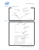
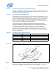
Figure 2-7. LGA2011-1 Socket Features
Cavity
Processor
keying (4x)
Seating Plane
Finger Access
Housing
ILM Keying
Contact Array (2x)
Package Alignment