
Guide


Thermal and Mechanical Design
Intel® Xeon® Processor E7 2800/4800/8800 v2 Product Family 41
Thermal/ Mechanical Specifications and Design Guide
2.2.2 T
CASE
and DTS Based Thermal Specifications
To simplify compliance to thermal specifications at processor run time, processor has
added a Digital Thermal Sensor (DTS) based thermal specification. Digital Thermal
Sensor reports a relative die temperature as an offset from TCC activation
temperature. T
CASE
thermal based specifications are used for heatsink sizing and DTS
based specs are used for acoustic and fan speed optimizations. For the Intel® Xeon®
Processor E7 2800/4800/8800 v2 Product Family, firmware (for example, BMC or other
platform management devices) will have DTS based specifications for all SKUs
programmed by the customer. SKUs may share T
CASE
thermal profiles but they will
have separate T
DTS
based thermal profiles.
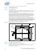
The processor fan speed control is managed by comparing DTS thermal readings via
PECI against the processor-specific fan speed control reference point, or Tcontrol. Both
T
CONTROL
and DTS thermal readings are accessible via the processor PECI client. At a
one time readout only, the Fan Speed Control firmware will read the following:
• IA32_TEMPERATURE_TARGET MSR
• Tcontrol via PECI - RdPkgConfig()
• TDP via PECI - RdPkgConfig()
• Core Count - RdPCIConfigLocal()
DTS PECI commands will also support DTS temperature data readings. Please see “DTS
Temperature Data” section of the processor datasheet for PECI command details.
Notes:
1. SKUs are subject to change. Please contact your Intel Field Representative to obtain the latest SKU
information.
2. These values are specified at V
CC_MAX
for all processor frequencies. Systems must be designed to ensure
the processor is not to be subjected to any static V
CC
and I
CC
combination wherein V
CC
exceeds V
CC_MAX
at
specified ICC.
3. Thermal Design Power (TDP) should be used for processor thermal solution design targets. TDP is not the
maximum power that the processor can dissipate. TDP is measured at maximum T
CASE
.
4. Tcase (Y) at a particular power is obtain by applying the thermal profile and replacing (X) with the desired
power value. Tcase_max per specific SKU may be obtained by replacing (X) with the SKU TDP value.
5. These specifications are based on initial pre-silicon simulations, which will be updated as further
characterization data becomes available.
6. Power specifications are defined at all VIDs. Processor may be delivered under multiple VIDs for each
frequency.
7. FMB, or Flexible Motherboard, guidelines provide a design target for meeting all planned processor
frequency requirements.
8. Some processor units may be tested to lower TDP and the IA32_TEMPERATURE_TARGET MSR will be
aligned to that lower TDP.
Table 2-10. Processor SKU Thermal Profiles
TDP
Core
Count
Minimum
T
CASE
(°C)
Tcase_max
@ TDP (°C)
Thermal Profile
T
CONTROL
Tcase DTS
155 W
15
5 77 Y=0.184X+49.0
Y=0.258X+49.0 10
10 Y=0.310X+49.0 15
6 Y=0.361X+49.0 10
130 W
15
5 73 Y=0.185X+49.0
Y=0.262X+49.0 10
12 Y=0.262X+49.0 10
105 W
15
5 68 Y=0.181X+49.0
Y=0.248X+49.0 10
12 Y=0.248X+49.0 10
10 Y=0.305X+49.0 10
8
Y=0.305X+49.0 10
6 Y=0.352X+49.0 10