
Guide


Thermal and Mechanical Design
Intel® Xeon® Processor E7 2800/4800/8800 v2 Product Family 29
Thermal/ Mechanical Specifications and Design Guide
baseboard and system must be considered when designing the heatsink and ILM
attach mechanism. Their design should provide a means for protecting the
LGA2011-1 socket solder joints as well as preventing package pullout from
the socket.
Note: The load applied by the attachment mechanism and the heatsink must comply with the
package specifications, along with the dynamic load added by the mechanical shock
and vibration requirements.
Note: Load induced onto the package and socket by the ILM may be influenced with heatsink
installed. Determining the performance for any thermal/mechanical solution is the
responsibility of the customer.
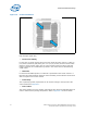
A potential mechanical solution for heavy heatsink is the use of a supporting
mechanism such as a backer plate or the utilization of a direct attachment of the
heatsink to the chassis pan. In these cases, the strength of the supporting component
can be utilized rather than solely relying on the baseboard strength. In addition to the
general guidelines given above, contact with the baseboard surfaces should be
minimized during installation in order to avoid any damage to the baseboard.
Placement of board-to-chassis mounting holes also impacts board deflection and
resultant socket solder ball stress. Customers need to assess the shock for their
designs as heatsink retention (back plate), heatsink mass and chassis mounting holes
may vary.
2.1.4 Mechanical Load Specifications
2.1.4.1 ILM Load Specifications
The ILM is designed to achieve the minimum Socket Static Pre-Load Compressive load
specification. The minimum Static Pre-Load Compressive load is the force provided by
the ILM and should be sufficient for rudimentary continuity testing of the socket and/or
board. This load value will not ensure normal operation throughout the life of the
product. Please see Table 2-7.
The thermal solution (heatsink) should apply additional load to achieve the Socket
Static Total Compressive load (see Table 2-5). The heatsink load will be applied to the
IHS (Integrated Heat Spreader). The dual-loading approach is represented by the
following equation:
F
ILM
+ F
HEATSINK
= F
SOCKET
Table 2-7 provides load specifications for the ILM and heatsink. The maximum limits
should not be exceeded during assembly, shipping conditions, or standard use
condition. Exceeding these limits may result in component failure. The socket body or
the processor substrate should not be used as a mechanical reference or load-bearing
surface for the thermal solution.
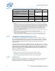
Table 2-7. ILM and Heatsink Mechanical Load Specifications (Sheet 1 of 2)
Parameter Min Max Notes
Total Static Compressive Load BOL (HS+ILM) 667 N [150 lbf] 1068 N [240 lbf] 1, 2
Heatsink Static Compressive Load BOL 222 N [50 lbf]
356 N [80 lbf] 1, 3, 4, 5
Heatsink Static Compressive Load EOL 178 N [40 lbf]