L440GX+ Server Board Product Guide Order Number: 722077-005
Disclaimer Intel Corporation (Intel) makes no warranty of any kind with regard to this material, including, but not limited to, the implied warranties of merchantability and fitness for a particular purpose. Intel assumes no responsibility for any errors that may appear in this document. Intel makes no commitment to update nor to keep current the information contained in this document. No part of this document may be copied or reproduced in any form or by any means without prior written consent of Intel.
Contents 1 Description Server Board Features..........................................................................................................7 Back Panel Connectors................................................................................................8 Server Board Connector and Component Locations.....................................................9 Processor...................................................................................................................10 Memory ......
Setup Menus ..............................................................................................................36 Main Menu .................................................................................................................37 Advanced Menu .........................................................................................................40 Security Menu ............................................................................................................43 Server Menu...
4 Solving Problems Resetting the System ..........................................................................................................85 Fault Resilient Booting ........................................................................................................85 Initial System Startup ..........................................................................................................85 Checklist ..........................................................................................
Ensure Host Computer and Accessory Module Certifications................................... 107 Prevent Power Supply Overload............................................................................... 107 Place Battery Marking on Computer......................................................................... 108 Use Only for Intended Applications .......................................................................... 108 Installation Precautions .....................................................
1 Description Server Board Features Table 1. Server Board Features Feature Description Processor Installed: Up to two Intel® Pentium® II or Pentium III processors (with 100 MHz system bus) operating at 1.8 V to 3.5 V. The server board’s voltage regulator is automatically programmed by the processor’s VID pins to provide the required voltage.
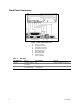
Back Panel Connectors Figure 1. Back Panel Connectors A. B. C. D. E. F. G. H. I. Table 2. 8 Mouse connector Keyboard connector Parallel Port connector Serial Port connectors Network connector Green NIC LED Orange NIC LED USB connectors Video connector NIC LEDs NIC LED Color If it's on If it's blinking If it's off Orange 100 Mbps network connection. NA 10 Mbps network connection. Green Linked to network, no network traffic. Linked to network, sending or receiving data. Not linked to network.
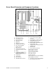
Server Board Connector and Component Locations Figure 2. Server Board Connector and Component Locations A. B. C. D. E. F. G. H. I. J. K. L. M. N. Fansink connector 2 Secondary processor Fansink connector 1 Primary processor DIMM slots Main power connector ATX Aux power connector Fan connector FAN2A Floppy connector IDE connectors ATX front panel connector Front panel connector, 16 pin Battery Isolated Server Management (ISOL) IMB (Intelligent Management Bus) connector O. Jumper block P. Jumper block Q.
Processor Each Pentium II or Pentium III processor is packaged in a cartridge. The cartridge includes the processor core with an integrated 16 KB primary (L1) cache, the secondary (L2) cache, and a back cover. The processor implements the MMX™ technology and maintains full backward compatibility with the 8086, 80286, Intel386™, Intel486™, Pentium, Pentium Pro and previous Pentium II processors.
/ NOTE Use DIMMs that have been tested for compatibility with the server board. Contact your sales representative or dealer for a current list of approved memory modules. Check the Intel Customer Support website for the latest tested memory list: http://support.intel.com/support/motherboards/server/l440gx/compat.htm 440GX Host Bridge / Memory Controller The L440GX+ is designed around the Intel® 82440GX AGPSet (440GX).
Add-in Board Slots The server board has one full length ISA bus connector. ISA features: • • • • • • Bus speed up to 8.33 MHz 16 bit memory addressing Type A transfers at 5.33 Mbps Type B transfers at 8 Mbps 8 or 16 bit data transfers Plug and Play ready The server board has four full length standard PCI (PCI-33/32 bit) connectors.
Video The onboard, integrated Cirrus Logic CL-GD5480 64 bit VGA chip contains an SVGA controller that is fully compatible with these video standards: CGA, EGA, Hercules† Graphics, MDA, and VGA. The standard configuration comes with 2 MB of 10 ns onboard Synchronous Graphics Memory (SGRAM). The video controller supports pixel resolutions of up to 1600 x 1200 and up to 16.7 Million colors.
/ NOTE 18 inch maximum length of IDE cable on each channel: You can connect an IDE signal cable, up to a maximum of 18 inches each, to each IDE connector on the server board. Each cable can support two devices, one at the end of the cable and one 6 inches from the end of the cable. Network Controller The server board includes a 10BASE-T/100BASE-TX network solution based on the Intel 82559 single chip Fast Ethernet PCI Bus Controller. As a PCI bus master, the controller can burst data at up to 132 MB/s.
future versions of Microsoft Windows NT†x that support ACPI, the BIOS will support sleep states s0, s1, s4, and s5. • • • • s0: Normal running state. s1: Processor sleep state. No context will be lost in this state and the processor caches will maintain coherency. s4: Hibernate or Save to Disk: The memory and machine state are saved to disk. Pressing the power button or other wakeup event will restore the system state from the disk and resume normal operation.
• • • • • • • • • • Monitors the SDR/SEL timestamp clock Manages the server board Field Replaceable Unit (FRU) information interface Monitors the system management watchdog timer Monitors the periodic SMI timer Manages front panel NMI handling Monitors the event receiver Manages the ISA host and IMB interface Controls secure mode, including video blanking, floppy write-protect monitoring, and front panel lock/unlock initiation Manages the sensor event initialization agent Controls Wake on LAN via Magic Pac
Security To help prevent unauthorized entry or use of the server, Intel Server Control server management software monitors the system intrusion switch. Security with Mechanical Locks and Monitoring If installed, you can activate the chassis intrusion alarm switch. When the side door is opened, the switch transmits an alarm signal to the server board, where BMC firmware and server management software process the signal.
• • May enter either password to boot the server if Password on Boot is enabled in either the BIOS Setup or SSU. May enter either password to exit secure mode. Secure Mode Configure and enable the secure boot mode by using the SSU. When secure mode is in effect: • You can boot the server and the operating system will run, but you must enter the user password to use the keyboard or mouse. • You cannot turn off system power or reset the server from the front panel switches.
Summary of Software Security Features The table below lists the software security features and describes what protection each offers. In general, to enable or set the features listed here, you must run the SSU and go to the Security Subsystem Group, menu. The table also refers to other SSU menus and to the Setup utility. Table 3. Software Security Features Feature Description Secure mode How to enter secure mode: • Setting and enabling passwords automatically places the system in secure mode.
Table 3. Software Security Features (continued) Feature Description Control access to the system other than SSU: set user password To control access to using the system, set a user password and enable it through Setup or the SSU. To disable a password, change it to a blank entry or press CTRL-D in the Change Password menu of the User Password Option menu found in the Security Subsystem Group. To clear the password if you cannot access Setup or the SSU, change the Clear Password jumper (see Chapter 5).
2 Upgrading Tools and Supplies Needed • • • • Phillips (cross head) screwdriver (#1 bit and #2 bit) Jumper removal tool or needle nosed pliers Pen or pencil Antistatic wrist strap and conductive foam pad (recommended) Warnings and Cautions These warnings and cautions apply throughout this chapter. Only a technically qualified person should configure the server board. WARNINGS System power on/off: The power button DOES NOT turn off the system AC power.
top that you can grip with your fingertips or with a pair of fine needle nosed pliers. If your jumpers do not have such a tab, take care when using needle nosed pliers to remove or install a jumper; grip the narrow sides of the jumper with the pliers, never the wide sides. Gripping the wide sides can damage the contacts inside the jumper, causing intermittent problems with the function controlled by that jumper.
Figure 3. Server Board Screw Hole Locations Removing the Server Board CAUTION The server board can be extremely sensitive to ESD and always requires careful handling. After removing it from the server, place it component side up on a nonconductive, static free surface to prevent shorting out the battery leads. If you place the board on a conductive surface, the battery leads may short out. If they do, this will result in a loss of CMOS data and will drain the battery.
Memory Installing DIMMs CAUTIONS Use extreme care when installing a DIMM. Applying too much pressure can damage the socket. DIMMs are keyed and can be inserted in only one way. Mixing dissimilar metals may cause later memory failures resulting in data corruption. Only install DIMMs with gold-plated edge connectors in gold-plated sockets. See Chapter 1 for memory size and requirements. 1. Observe the safety and ESD precautions at the beginning of this chapter. 2. Open your server. 3.
Figure 4. Installing DIMMs Removing DIMMs CAUTION Use extreme care when removing a DIMM. Too much pressure can damage the socket slot. Apply only enough pressure on the plastic ejector levers to release the DIMM. 1. 2. 3. 4. 5. 6. 7. 8. Observe the safety and ESD precautions at the beginning of this chapter. Open the server. Gently push the plastic ejector levers out and down to eject a DIMM from its socket.
Processors WARNING If the server has been running, any installed processor and heat sink on the processor board(s) will be hot. To avoid the possibility of a burn, be careful when removing or installing server board components that are located near processors. CAUTIONS Processor must be appropriate: You may damage the server if you install a processor that is inappropriate for your server. Make sure your server can handle a newer, faster processor (thermal and power considerations).
CAUTION This is a difficult process. Do not pull the tab of the retention mechanism back too far, as damage to either the retention mechanism or server board can occur. Pull the tab of the retention mechanism back just far enough for the retention lock to free the processor. 4. Put the processor in a piece of conductive foam and store in an antistatic package. Figure 5. Installing a Processor A. B.
Installing a Processor 1. Observe the safety and ESD precautions at the beginning of this chapter and the additional cautions given here. 2. If your server has one processor and you are ADDING a second, then you must remove the termination card from the secondary processor slot. Carefully pull back the tab of the retention mechanism with your left hand until the processor can be rotated out of the slot.
3. If your server has one processor and you are REPLACING it, leave the termination board intact in the empty secondary slot. Remove the processor you want to replace. See “Removing a Processor” on page 26. 4. If your server has two processors and you are REPLACING one or both, remove the appropriate one(s). See “Removing a Processor” on page 26. 5. Remove the new processor from its antistatic package and place it on a grounded, static free surface or conductive foam pad. 6.
Replacing the Back up Battery The lithium battery on the server board powers the real time clock (RTC) for up to 10 years in the absence of power. When the battery starts to weaken, it loses voltage, and the server settings stored in CMOS RAM in the RTC (for example, the date and time) may be wrong. Contact your customer service representative or dealer for a list of approved devices. WARNING Danger of explosion if battery is incorrectly replaced.
Figure 7. Replacing the Lithium Battery 1. Observe the safety and ESD precautions at the beginning of this chapter. 2. Open the chassis. 3. Insert the tip of a small flat bladed screwdriver, or equivalent, under the tab in the plastic retainer. 4. Gently push down on the screwdriver to lift the battery. 5. Remove the battery from its socket. 6. Dispose of the battery according to local ordinance. 7.
Upgrading
3 Configuration Software and Utilities This chapter describes the Power On Self Test (POST) and server configuration utilities. The table below briefly describes the utilities. Table 4. Configuration Utilities Utility Description and brief procedure Page BIOS Setup If the system does not have a diskette drive, or the drive is disabled or misconfigured, use Setup to enable it.
Power On Self Test (POST) Each time you turn on the system, POST starts running. POST checks the server board, processor, memory, keyboard, and most installed peripheral devices. During the memory test, POST displays the amount of memory that it is able to access and test. The length of time needed to test memory depends on the amount of memory installed. POST is stored in flash memory. 1. Turn on your video monitor and server. After a few seconds POST begins to run. 2.
Using BIOS Setup This section describes the BIOS Setup options. Use Setup to change the server configuration defaults. You can run Setup with or without an operating system being present. Setup stores most of the configuration values in battery backed CMOS; the rest of the values are stored in flash memory. The values take effect when you boot the server. POST uses these values to configure the hardware; if the values and the actual hardware do not agree, POST generates an error message.
Starting Setup You can enter and start Setup under several conditions: • When you turn on the server, after POST completes the memory test • When you reboot the server by pressing while at the DOS operating system prompt • When you have moved the CMOS jumper on the server board to the “Clear CMOS” position (enabled); for the procedure, see Chapter 5, under the heading “CMOS Jumper” In the three conditions listed above, after rebooting, you will see this prompt: Press to enter SETUP In a
Main Menu You can make the following selections on the Main Menu itself. Use the submenus for other selections. Feature Choices Description System Time HH:MM:SS Sets the system time. System Date MM/DD/YYYY Sets the system date. Legacy Diskette A: Disabled 360KB 1.2 MB 720KB 1.44/1.25 MB 2.88 MB Selects the diskette type. Legacy Diskette B: Disabled 360KB 1.2 MB 720KB 1.44/1.25 MB 2.88 MB Primary IDE Master Enters submenu. Primary IDE Slave Enters submenu.
Primary/Secondary IDE Master and Slave Submenu Feature Choices Description Type Auto None CD-ROM IDE Removable Auto forces the server to attempt autodetection of the drive type. None informs the server to ignore this drive. CD ROM allows the manual entry of some fields described below. IDE Removable allows the manual entry of some fields described below. ATAPI Removable allows the manual entry of some fields described below. User allows the manual entry of all fields described below.
Keyboard Submenu Feature Choices Description Num Lock On Off Selects the power on state for Num Lock. Key Click Disabled Enabled Enables or disables the audible key click. Keyboard auto-repeat rate 30/sec 26.7/sec 21.8/sec 18.5/sec 13.3/sec 10/sec 6/sec 2/sec Sets the numbers of time per second a key will repeat while it is held down. Keyboard auto-repeat delay 1/4 sec 1/2 sec 3/4 sec 1 sec Sets the delay before a key starts to repeat when it is held down.
Advanced Menu You can make the following selections on the Advanced Menu itself. Use the submenus for the three other selections that appear on the Advanced Menu. Feature Choices Description Installed OS Other Win95 Select Win95 if you are booting a Plug and Play capable operating system. Reset Configuration Data No Yes Select Yes if you want to clear the server configuration data during next boot. System automatically resets to No in next boot. PCI Configuration Enters submenu.
PCI Device, Slot 1 - Slot 6 Submenus Feature Choices Description Enable Master Enabled Disabled Enables selected device as a PCI bus master. Latency Timer Default 020h 040h 060h 080h 0A0h 0C0h 0E0h Minimum guaranteed time, in units of PCI bus clocks, that a device may be master on a PCI bus. CAUTION Do not change this setting unless you fully understand the priority of this device on the PCI bus.
Integrated Peripheral Configuration Submenu (continued) Feature Choices Description Interrupt IRQ 5 IRQ 7 Selects the IRQ for LPT port. DMA channel DMA 1 DMA 3 Selects the DMA for LPT port (only used for ECP mode). Floppy disk controller Disabled Enabled Enables onboard diskette controller. Advanced Chipset Control 42 Feature Choices Description 640-768K Memory Region Enabled Disabled Enabled forwards ISA Master and DMA cycles to the PCI bus. Disabled forwards these cycles to memory.
Security Menu You can make the following selections on the Security Menu itself. Enabling the Supervisor Password field requires a password for entering Setup. The passwords are not case-sensitive. Feature Choices Description User Password is Clear Set Status only; user cannot modify. Once set, this can be disabled by setting it to a null string, or by clearing password jumper on server board. Supervisor Password is Clear Set Status only; user cannot modify.
Server Menu You can make the following selections on the Server Menu itself. Feature Choices Description System Management Enters submenu. Console Redirection Enters submenu. PEP Management Enters submenu. Enable Sleep Button Disabled Enabled PCI IRQs to IO-APIC mappings Disabled Enabled Enabled - BIOS can describe all 24 IO APIC pins in the MP table for PCI interrupts. Not all MP operating systems and drivers can understand this description of the interrupts in the MP table.
System Management Submenu (continued) Feature Choices Description EMP Hangup Line String ATH Sets the Hangup Line Sequence for the modem being used for EMP. Used in EMP modem mode. Modem Init String AT&F0S0=1S14=0&D Sets the initialization string for the modem being used for EMP. Used in EMP modem mode. This field is only 16 characters long. The High Modem Init String field is a continuation of the Modem Init string so you can enter in another 4 characters.
Console Redirection Submenu Feature Choices Description COM Port Address Disabled 3F8 2F8 3E8 When enabled, console redirection uses the I/O port specified. 3F8 - typically is COM1 2F8 - typically is COM2 All keyboard/mouse and video will be directed to this port. This is designed to be used only under DOS in text mode. 46 IRQ # N/A This field is informational only. Baud Rate 9600 19.2k 38.4k 115.2k When console redirection is enabled, specifies the baud rate to be used.
PEP Management Submenu Verify in BIOS Setup of your server board whether or not your system BIOS includes PEP. If not, when it becomes available, you can download it from the Intel Customer Support website: http://support.intel.com/support/motherboards/server/l440gx Feature Choices PEP Filter Events Description Enters submenu. PEP Enable Disable Enable Enables Platform Event Paging. PEP Blackout Period [0…9] Sets the amount of time between pages in minutes. Valid range is from 0 to 10.
PEP Filter Submenu This submenu allows you to set which events or error conditions cause the system to page you. Feature Choices Description PEF Enable Disable Enable Enables the Platform Event Filtering. If this is enabled, and one of the events you enable below occurs, the server will page you using the Page String (NV) information.
Extended RAM Step Choice Description 1 MB Tests extended memory once per MegaByte 1 KB Tests extended memory once per KiloByte Every Location Tests all extended memory No Memory test No extended memory is tested Boot Device Priority Use the up or down arrow keys to select a device; then press the <+> or <-> keys to move the device higher or lower in the boot priority list. Boot Priority Device Description 1. Removable Devices Attempts to boot from a removable media device. 2.
Removable Devices For options on this menu, use the up or down arrow keys to select a device, then press the <+> or <-> keys to move the device higher or lower in the boot priority list. Option Description 1. Legacy Floppy Drive Refers to the onboard 3.5” floppy drive. Removable IDE media may also show up here if the removable media was formatted in floppy emulation. Exit Menu You can make the following selections on the Exit Menu.
When to Run the System Setup Utility The SSU is a DOS-based utility that supports extended system configuration operations for onboard resources and add-in boards. You can also view the system event log and to set system boot and security options.
Running the SSU • • Running the SSU Locally Running the ssu.bat file provided on the SSU media starts the SSU. If the server boots directly from the SSU media, the ssu.bat file is automatically run. If it boots from a different media, the SSU can be started manually or by another application. When the SSU starts in the local execution mode (the default mode), the SSU accepts input from the keyboard and/or mouse. The SSU presents a VGA based Graphical User Interface (GUI) on the primary monitor.
5. This message appears: Please wait while the Application Framework loads.... 6. When the main window of the SSU appears, you can customize the user interface before continuing. Figure 8.
Customizing the SSU The SSU lets you customize the user interface according to your preferences. The AF sets these preferences and saves them in the AF.INI file so that they take effect the next time you start the SSU. There are four user customizable settings: • Color - this button lets you change the default colors associated with different items on the screen with predefined color combinations. The color changes are instantaneous. • Mode - this button lets you set the desired expertise level.
Resource Configuration Add-in (RCA) Window The RCA provides three major functions: • Creates representations of devices that cannot be discovered by the system (ISA cards) • Modifies the contents of the system by adding and removing devices • Modifies the resources used by devices You can use the RCA window to define an ISA card or add an ISA card by clicking on the appropriate button.
Adding and Removing ISA Cards Adding and removing cards through the RCA provides a way for the RCA to run its conflict detection algorithms on the resources requested by the cards. This alerts you to any possible problems with that particular card in the current configuration. • • To add an ISA card: 1. Click on Add ISA Card in the RCA window. 2. Specify the directory for the .CFG file. 3. Select the file and click on Ok. To remove an ISA card: 1.
Security Add-in Under this window, you can set the User and Administrator passwords, and security options. To Set the User Password 1. Click on the user password button. 2. Enter the password in the first field. 3. Confirm the password by entering it again in the second field. To Change or Clear the User Password 1. 2. 3. 4. Click on the User password button. Enter the old password in the first field. Enter the new password in the second field (or leave blank to clear).
SEL Manager Add-in Clicking on the SEL Manager Add-in task brings up the Server Event Log (SEL) viewer. You can load and view the current SEL data stored in the BMC, save the currently loaded SEL data to a file, view previously saved SEL data, or clear the SEL. The SEL Viewer has the following menus: File The File menu has the following options: • Load SEL… View data from a previously saved SEL file. • Save SEL… Save the currently loaded SEL data to a file. • Clear SEL Clears the SEL data from the BMC.
FRU Manager Add-in Clicking on the FRU Manager Add-in task brings up the Field Replaceable Unit (FRU) viewer. You can load and view the current FRU data stored in the BMC, save the currently loaded FRU data to a file, view previously saved FRU data. The FRU Viewer has the following menus: File The File menu has the following options: • Load… View data from a previously saved FRU file. • Save… Saves the currently loaded FRU data to a file. • Save As… Saves the currently loaded FRU data to a file.
SDR Manager Add-in Clicking on the SDR Manager Add-in task brings up the Sensor Data Record (SDR) viewer. You can load and view the current SDR data stored in the BMC, save the currently loaded SDR data to a file, view previously saved SDR data. The SDR Viewer has the following menus: File The File menu has the following options: • Load… View data from a previously saved SDR file. • Save… Saves the currently loaded SDR data to a file. • Save As… Saves the currently loaded SDR data to a file.
Platform Event Paging With Platform Event Paging (PEP), your server can be configured to automatically dial up a paging service and page you when a server management related event occurs. Platform events include temperature out-of-range, voltage out-of-range, chassis intrusion, and fan failure. If PEP is enabled and the BMC receives or detects a new event, it automatically sends a page. It can send a page if the processors are down or if the system software is unavailable.
Emergency Management Port Console The Emergency Management Port (EMP) Console is a software application designed to run on a Windows 95 or Windows NT 4.0 workstation and provides a server administrator’s interface to the Emergency Management Port (EMP) of the L440GX+ server. This interface allows remote server management via a modem or direct connection.
How EMP Console Works The EMP shares use of the COM2 port with the system on the server. When the EMP has control of the port, the port operates in command mode. When the system has control, the port operates in console redirect mode. When connecting to a server, the EMP Console checks to determine the mode of the COM2 port. The following discussion covers how EMP Console functions in each mode: • Command mode is the default COM2 state.
Figure 10. EMP Console in Redirect State Figure 10 shows EMP Console window in redirect mode with the terminal window. The text that appears on the server monitor displays in the Redirect window. Availability of the various EMP Console features are determined by two factors: the BIOS EMP access mode and if the server's COM2 port is configured for console redirection. The three EMP access modes are disabled, pre-boot, and always active. Table 6.
Table 7.
Setting up the Server for the EMP To use the EMP, you must configure the server's BIOS with specific settings. These settings are found in two submenus of the BIOS Server menu, the System Management Submenu and the Console Redirection submenu. The BIOS settings section, found earlier in this document, shows all the available options. This section focuses on the settings that must be configured in order to use the EMP. System Management Submenu All EMP related settings occur in the Server main menu.
Main EMP Console Window The main EMP Console window provides a graphical user interface (GUI) to access server control operations and to launch the management plug-ins. At the top of the window is the menu and tool bar. These provide the options to initiate plug-ins and other support features. A status bar at the bottom displays connection information such as server name, line status, and mode.
EMP Console Main Menu • • • • File Exit - exits EMP Console. Connect Disconnect - disconnects the server connection. [Re]Connect - displays the connect dialog. A list of the five most recent modem connections. Click on one of these server names to initiate a connection. Action Power On/Off - displays the Power on/off dialog. Reset - displays the Reset dialog. SEL Viewer - displays the SEL Viewer. SDR Viewer - displays the SDR Viewer. FRU Viewer - displays the FRU Viewer.
Connect When [Re]Connect is selected from the Connect menu, the Connect dialog in Figure 11 is displayed. This dialog allows you to connect to a server. If the client machine is already connected to a server, initiating connection generates a warning message. The message indicates that the existing connection will be terminated if you continue trying to initiate the new connection. You are prompted to enter the EMP password whenever a connection is attempted. Figure 11.
Power On/Off Selecting Power On/Off from the Action menu displays the Power on/off dialog. This dialog provides commands to remotely power on or power off the server. Figure 12. Power On/Off Dialog Options available in the dialog are: • Power ON - powers on the server. • Power OFF - powers off the server. This option is not allowed if the server is configured in RESTRICTED mode for EMP operations. • Post-power-up option - sets the mode selection of the server to EMP active or BIOS redirection.
Options available in the dialog are: • System Reset - resets the server with the selected post-reset options. This operation is not allowed if the server is configured in RESTRICTED mode for EMP operations. • Post-reset option - sets the post-reset option that will be in effect after reset. The options are EMP active or BIOS redirection. The default selection is EMP active. • Cancel - exits the Connect dialog without taking any action. • Help - displays the help information for this dialog.
• • • Connect - displays the Connect dialog with the server from the Phonebook's Server dropdown list box already populating the Connect dialog's Server field. Cancel - exits the Connect dialog without taking any action. Help - displays the help information for this dialog. Management Plug-ins SEL Viewer The SEL Viewer provides access to the System Event Log on the server and can display records in either hexadecimal or text (verbose) form.
• • By Event - displays all the events in the SEL of a particular event type; for example, threshold, digital, or discrete. A pop-up menu lets you select the event type to be displayed. Settings - changes several operating parameters for the SEL Viewer. This menu displays the following suboptions: • Display HEX/Verbose - toggles between HEX mode and interpreted mode of displaying SEL records.
FRU Viewer The FRU Viewer allows you to view the server's FRU (Field Replaceable Unit) data from the server's Front Panel FRU information area. The options available in the FRU Viewer are: • • • • • View all FRU records View FRU summary info Set FRU display mode to either Hex or verbose mode Close the FRU Viewer Exit EMP Console FRU Viewer Menu Options The following menu options are found on the FRU Viewer menu bar: • • • • • 74 File Close - closes the FRU Viewer. Exit - exits EMP Console.
FRUSDR Load Utility The Field Replacement Unit (FRU) and Sensor Data Record (SDR) Load Utility is a DOS-based program used to update the server management subsystem’s product level FRU, SDR, and the Desktop Management Interface (DMI) nonvolatile storage components (EEPROMs).
How You Use the FRUSDR Load Utility This utility is compatible with ROM-DOS Ver. 6.22, MS-DOS† Ver. 6.22, and later versions. The utility accepts CFG, SDR and FRU load files. The executable file for the utility is frusdr.exe. The utility requires the following supporting files: • • • one or more .fru files describing the system’s field replaceable units a .cfg file describing the system configuration a .
Displaying DMI Area The DMI area is displayed in ASCII format when the field is ASCII or as a number when the field is a number. Each DMI area displayed is headed with the DMI area designated name. Each field has a field name header followed by the field in ASCII or as a number. Displaying FRU Area The FRU area is displayed in ASCII format when the field is ASCII or as a number when the field is a number. Each FRU area displayed is headed with the FRU area designated name.
Updating the SDR Nonvolatile Storage Area After the utility validates the header area of the supplied SDR file, it updates the SDR repository area. Before programming, the utility clears the SDR repository area. The SDR file is loaded via the .cfg File. Then the utility filters all tagged SDRs depending on the product configuration set in the Configuration File. Nontagged SDRs are automatically programmed. The utility also copies all written SDRs to the SDR.TMP file.
Upgrading the BIOS Preparing for the Upgrade Before you upgrade the BIOS, prepare for the upgrade by recording the current BIOS settings, obtaining the upgrade utility, and making a copy of the current BIOS. Recording the Current BIOS Settings 1. Boot the computer and press when you see the message: Press Key if you want to run SETUP 2. Write down the current settings in the BIOS Setup program. / NOTE Do not skip step 2.
Creating the BIOS Upgrade Floppy Diskette The BIOS upgrade file is a compressed self-extracting archive that contains the files you need to upgrade the BIOS. 1. Copy the BIOS upgrade file to a temporary directory on your hard disk. 2. From the C:\ prompt, change to the temporary directory. 3. To extract the file, type the name of the BIOS upgrade file, for example: 10006BI1.EXE 4. Press . The extracted file contains the following files: LICENSE.TXT README.TXT BIOS.EXE 5. Read the LICENSE.
Recovering the BIOS It is unlikely that anything will interrupt the BIOS upgrade; however, if an interruption occurs, the BIOS could be damaged. The following steps explain how to recover the BIOS if an upgrade fails. The following procedure use recovery mode for the Setup program. / NOTE Because of the small amount of code available in the nonerasable boot block area, there is no video support. You will not see anything on the screen during the procedure.
Using the Firmware Update Utility The Firmware Update Utility is a DOS-based program used to update the Baseboard Management Controller’s firmware code. You only need to run the Firmware Update Utility if new firmware code becomes necessary. Running the Firmware Update Utility 1. Create a DOS bootable diskette. The version of DOS must be 6.0 or higher. 2. Place the firmware update utility (FWUPDATE.EXE) and the *.hex file on the diskette. Make a note of the *.hex file name, you will need it later. 3.
Using the Adaptec SCSI Utility The Adaptec SCSI utility detects the SCSI host adapters on the server board. The utility runs out of BIOS and is used to • • Change default values Check and/or change SCSI device settings that may conflict with those of other devices in the server Running the SCSI Utility 1. When this message appears on the video monitor: Press Ctrl-A to run SCSI Utility... 2. Press to run this utility. When it appears, choose the host adapter that you want to configure.
Configuration Software and Utilities
4 Solving Problems This chapter helps you identify and solve problems that might occur while you are using the system. Resetting the System To do this: Press: Soft boot reset, which clears system memory and reloads the operating system. Clear system memory, restart POST, and reload the operating system. Reset button Cold boot reset. Turn the system power off and then on. This clears system memory, restarts POST, reloads the operating system, and halts power to all peripherals.
Checklist q Are all cables correctly connected and secured? q Are the processors or processor termination board fully seated in their slots on the server board? q Are all add-in ISA and PCI boards fully seated in their slots on the server board? q Are all switch and jumper settings on the server board correct? q Are all jumper and switch settings on add-in boards and peripheral devices correct? To check these settings, refer to the manufacturer’s documentation that comes with them.
After the System Has Been Running Correctly Problems that occur after the system hardware and software have been running correctly often indicate equipment failure. Many situations that are easy to correct, however, can also cause such problems. Checklist q If you are running the software from a diskette, try a new copy of the software. q If you are running the software from a CD-ROM disk, try a different disk to see if the problem occurs on all disks.
More Problem Solving Procedures This section provides a more detailed approach to identifying a problem and locating its source. Preparing the System for Diagnostic Testing CAUTION Turn off devices before disconnecting cables: Before disconnecting any peripheral cables from the system, turn off the system and any external peripheral devices. Failure to do so can cause permanent damage to the system and/or the peripheral devices. 1. Turn off the system and all external peripheral devices.
Specific Problems and Corrective Actions This section provides possible solutions for these specific problems: • Power light does not light. • There is no beep or an incorrect beep pattern. • No characters appear on screen. • Characters on the screen appear distorted or incorrect. • System cooling fans do not rotate. • Diskette drive activity light does not light. • Hard disk drive activity light does not light. • CD-ROM drive activity light does not light. • There are problems with application software.
3. If there are still no characters on the screen after you reboot the system and POST emits a beep code, write down the beep code you hear. This information is useful for your service representative. See “Port-80 Codes and Countdown Codes” on page 94. 4. If you do not receive a beep code and characters do not appear, the video display monitor or video controller may have failed. Contact your service representative or authorized dealer for help.
Diskette Drive Activity Light Does Not Light Check the following: q Are the diskette drive power and signal cables properly installed? q Are all relevant switches and jumpers on the diskette drive set correctly? q Is the diskette drive properly configured? q Is the diskette drive activity light always on? If so, the signal cable may be plugged in incorrectly. If you are using the onboard diskette controller, use the SSU to make sure that “Onboard Floppy” is set to “Enabled.
/ NOTE Front panel hard disk LED indicates IDE and SCSI devices: The hard disk drive activity light on the front panel lights when either an IDE hard disk drive, or a SCSI device controlled by the onboard SCSI host controller, is in use. This LED does not display CD-ROM activity. Cannot Connect to a Server q Make sure you are using the drivers that are shipped on the system Configuration Software CD for the onboard network controller. q Make sure the driver is loaded and the protocols are bound.
The controller stopped working when an add-in adapter was installed. q Make sure the cable is connected to the port from the onboard network controller. q Make sure your PCI BIOS is current. Try the “PCI Installation Tips” below. q Make sure the other adapter supports shared interrupts. Also, make sure your operating system supports shared interrupts; OS/2† does not. q Try reseating the add in adapter. The add-in adapter stopped working without apparent cause.
Error and Informational Messages When you turn on the system, POST displays messages that provide information about the system. If a failure occurs, POST emits beep codes that indicate errors in hardware, software, or firmware. If POST can display a message on the video display screen, it causes the speaker to beep twice as the message appears.
5 Technical Reference This chapter includes the following: • Environmental specifications • Board interrupts • Electromagnetic Compatibility (EMC) notices 95
Connectors The figure shows connector locations on the server board. This section provides pin information about the connectors. Figure 15. Connector Locations A. B. C. D. E. F. G. H. 96 Fansink connector 2 Fansink connector 1 Main power connector ATX Aux power connector SM IMB Fan connector 2A ATX front panel connector Front panel connector, 16 pin I. J. K. L. M. N. O. P.
ATX Style Front Panel Connector Figure 16. ATX Style Front Panel Connector Table 8. ATX Style Front Panel Connector Pinout Connector A. Power switch Pin 1 2 3 Signal Power switch GND N/C B. Hard drive activity LED 4 5 6 7 Current limited +5V Key HD activity LED Current limited +5V C. Speaker 8 9 10 11 GND N/C PIEZO_IN SPKR_HDR D. Power LED 12 13 14 15 Current limited +5V N/C GND N/C E. Reset switch 16 17 GND Reset switch F.
Main Power Connector Table 9. Main Power Connector Pinout Pin Signal Pin Signal 1 +3.3V 13 +3.3V 2 +3.3V 14 -12V 3 COM 15 COM 4 +5V 16 PS_ON 5 COM 17 COM 6 +5V 18 COM 7 COM 19 COM 8 PWR_OK 20 -5V 9 +5VSB 21 +5V 10 +12V 22 +5V 11 +12V 23 +5V 12 +3.3V 24 COM Fan Interface The server board has five 3-pin fan connectors that are shrouded and keyed.
Server Board Jumpers Figure 17. Jumper Locations Table 11. Server Board Jumper Summary Jumper Block Jumper Name Pins (default in bold) What it does at system reset J5A2 WOL ENABLE 1-2, Disabled Disables Wake On LAN. If your power supply does not provide 0.8 A of +5 V Standby current, you must move the WOL Enable jumper to this position. 2-3, Enabled Enables Wake On LAN. J4J2 BMC WR EN 1-2, Protect BMC boot block is write protected.
Table 11. Server Board Jumper Summary (continued) Jumper Block Jumper Name Pins (default in bold) What it does at system reset J2J1 CMOS CLR 1-2, Protect Preserves the contents of NVRAM. 2-3, Erase Replaces the contents of NVRAM with the manufacturing default settings. 5-6, Protect Maintains the current system password. 6-7, Erase Clears the password. 9-10, Normal System attempts to boot using the BIOS stored in flash memory.
CMOS Jumper The jumper at pins 1, 2, and 3 controls whether settings stored in CMOS nonvolatile memory (NVRAM) are retained during a system reset. Procedure to restore the system’s CMOS and RTC to default values: 1. See “General Procedure to Change Jumper Setting” on page 100. 2. Move the CMOS jumper from pins 1 and 2 to pins 2 and 3 (the Clear CMOS memory position). 3. Reinstall the side cover for your safety, and connect the power cord to the system. 4. Turn the system on.
Recovery Boot Jumper The jumper at pins 9, 10, and 11 controls whether the system attempts to boot using the BIOS programmed in the boot block area of the FLASH memory. This should be used only if the operational area of the BIOS is corrupted or needs to be upgraded. Contact your local service representative before doing this. Procedure to disable recovery booting: 1. See “General Procedure to Change Jumper Setting” on page 100. 2. Move the recovery boot jumper from pins 9 and 10 to pins 10 and 11. 3.
Procedure to permit boot block erasing and programming: 1. See “General Procedure to Change Jumper Setting” on page 100. 2. Move the boot block jumper from pins 13 and 14 to pins 14 and 15 to erase and program the BIOS boot block. 3. Reinstall the side cover for your safety, and connect the power cord to the system. 4. Run the Boot Block Update Utility. 5. Turn off the system, and disconnect the power cord from the system. 6. Remove the side cover. 7.
Technical Reference
6 Regulatory and Integration Information Regulatory Compliance This server baseboard complies with the following safety and EMC regulations when correctly installed in a compatible host system. Table 12.
Installation Instructions CAUTION Follow these guidelines to meet safety and regulatory requirements when installing this board assembly. Read and adhere to all of these instructions and the instructions supplied with the host computer and associated modules.
Ensure Host Computer and Accessory Module Certifications Make sure that the host computer, any added subassembly (such as a board or drive assembly, including internal or external wiring), are certified for the region(s) where the end product will be used. Marks on the product are proof of certification. Certification marks are as follows: In Europe The CE marking signifies compliance with all relevant European requirements.
Place Battery Marking on Computer There is insufficient space on this server board to provide instructions for replacing and disposing of the battery. The following warning must be placed permanently and legibly on the host computer as near as possible to the battery. WARNING Danger of explosion if battery is incorrectly replaced. Replace with only the same or equivalent type recommended by the manufacturer. Dispose of used batteries according to the manufacturer’s instructions.
7 Equipment Log and Power Consumption Worksheets Equipment Log Use the blank equipment log provided here to record information about your system. You will need some of this information when you run the SSU.
Equipment Log (continued) Item 110 Manufacturer Name and Model Number Serial Number Date Installed Equipment Log and Power Consumption Worksheets
Current Usage As an overall current usage limitation on the power supply, do not exceed a combined power output of 167 watts for the +5 and +3.3 volt outputs. The ISA slots on the server board are rated at a maximum of 4.5 amperes per slot. The ISA specification recommends supporting an average of 2.0 amperes per slot. The average current usage should not exceed 3.0 amperes per slot; that is, 15 watts. The PCI slots on the server board are rated at a maximum of 5 amperes per slot.
Worksheet, Calculating DC Power Usage 1. List the current for each board and device in the appropriate voltage level column. 2. Add the currents in each column. Then go to the next worksheet. Table 14. Power Usage Worksheet 1 Current (maximum) at voltage level: Device +3.3 V +5 V –5 V +12 V –12 V Server board 1.0 A 8.0 A 0.1 A 1.1 A 0.4 A Primary Processor Secondary Processor (if present) Terminator card, if no second processor 1.6 A Memory (four 128 MB DIMMs) 1.8 A 0.
Worksheet, Total Combined Power Used by the System 1. From the previous worksheet, enter the total current for each column. 2. Multiply the voltage by the total current to get the total wattage for each voltage level. 3. Add the total wattage for each voltage level to arrive at a total combined power usage on the power supply. Table 15. Power Usage Worksheet 2 Voltage level and total current (V X A = W) Total Watts for each voltage level (+3.
Equipment Log and Power Consumption Worksheets
Index A Add-in boards IDE bus slots, 12 ISA, 51 ISA slots, 12 PCI, 51 administrative password, 17 limiting access to SCU, 19 Advanced Menu, configuring in Setup, 40 audible beep error codes, 34 B Back Panel Connectors, 8 battery disposing of safely, 30 installing, 31 removing, 30 beep codes, 34 BIOS changing the language, 81 recovering, 81 upgrading, 79 BIOS update utility, 33 BMC, 15 boot block write protect default jumper, 102 Boot Device Priority menu, configuring, Setup, 49 Boot menu, configuring, Setu
D diagnostics, preparing system for testing, 88 DIMM (memory) installing, 24 removing, 25 diskette drive controller, 13 enabling/disabling floppy writes, 19 no booting in secure mode without password, 19 reconfiguring if cannot enter Setup, 35 running SCU from, 33, 34 E Emergency Management Port FRU viewer, 74 main console window, 67 phonebook, 71 requirements, 65 SDR viewer, 73 server control operations, 68 Emergency Management Port Console, 16, 62 EMI, gasket for I/O connectors, 23 EMP.
M-N Main power supply, connector, 98 memory amount tested, POST, 34 capacity, 7 DIMM requirements, 11 DIMM size, 10 expansion, 10 installing DIMM, 24 removing DIMM, 25 video amount, 7 video size, 13 what type to install, 7 messages, error and informational, 94 monitoring server status, 15 mouse compatibility, 14 inactivity timer, 14 network, controller, 7, 14 P password, 17 administrative, 17 administrator, 18 entering to unblank screen, 19 retaining at system reset, 101 user, 17 using to reactivate keyboa
S SCI files, 51 SCSI, bus termination requirements, 13 SCSI controller, 13 SCU administrative password limits access to, 19 changing configuration, 33 diskette drive required to run SCU, 33 inactivity (lockout) timer, 14 software locking feature, 17 secure mode, 18 affects boot sequence, 20 enter by setting passwords, 19 locking reset and power on/off switches, 19 no booting from diskette without password, 19 using hot keys to enter, 33 security, 17, 19 alarm switches, 17 boot sequence, 20 enabling/disablin
System setup utility CFG files, 51 customizing, 54 defining an ISA card, 55 exiting, 60 launching a task, 54 location, 50 removing an ISA card, 56 running, 52 locally, 52 remotely, 52 SCI files, 51 when to run, 51 T-U termination board, removing, 28 timer keyboard or mouse inactive, 14 lockout (inactivity), setting in SCU, 14 upgrade Flash utility, 79 user password, 17 limit access to using system, 20 utilities BIOS update, 33 Emergency Management Port Console, 16, 62 Firmware update, 33, 82 FRUSDR load, 3
Index