Intel® IXDP465 Development Platform Quick Start Guide May 2005 Order Number: 305825, Revision: 002 May 2005
Legal Notice INFORMATION IN THIS DOCUMENT IS PROVIDED IN CONNECTION WITH INTEL® PRODUCTS. EXCEPT AS PROVIDED IN INTEL'S TERMS AND CONDITIONS OF SALE FOR SUCH PRODUCTS, INTEL ASSUMES NO LIABILITY WHATSOEVER, AND INTEL DISCLAIMS ANY EXPRESS OR IMPLIED WARRANTY RELATING TO SALE AND/OR USE OF INTEL PRODUCTS, INCLUDING LIABILITY OR WARRANTIES RELATING TO FITNESS FOR A PARTICULAR PURPOSE, MERCHANTABILITY, OR INFRINGEMENT OF ANY PATENT, COPYRIGHT, OR OTHER INTELLECTUAL PROPERTY RIGHT.
Intel® IXDP465 Development Platform—Contents Contents 1.0 Purpose .......................................................................................................................................... 5 2.0 Applicable Documents and Revisions ........................................................................................ 5 3.0 Known Issues ................................................................................................................................ 6 4.0 Inspection.....
Intel® IXDP465 Development Platform—Contents Revision History Date Revision Description Text updates for this release include: • Added paragraph about using zoom feature to read PDF in Section 1.0. (SCR 4282) • Added references to Intel® IXDP465 Development Platform Specification Update. • Added detail to procedure in Section 4.0. May 2005 002 • Added Section 5.1, “Emulation with the Intel® IXDP465 Development Platform” on page 8. • Clarified default settings for J127 and J128 in Table 4.
Quick Start Guide—Intel® IXDP465 Development Platform 1.0 Purpose This document, the Intel® IXDP465 Development Platform Quick Start Guide, contains instructions for unpacking, inspecting, setting up, and starting the Intel® IXDP465 Development Platform. Before the IXDP465 development platform is powered up for the first time, it is very important to first become familiar with the platform. Therefore, Section 5.0 through Section 8.
Intel® IXDP465 Development Platform—Quick Start Guide Table 1.
Quick Start Guide—Intel® IXDP465 Development Platform c. Re-seat the mezzanine card into the connector by applying finger pressure from one hand to the top-side of the mezzanine card directly over the connector while applying finger pressure from your other hand to the bottom-side of the base platform directly under the connector. Caution: Make sure that your fingers on both hands do not press against installed components on the assembly. d.
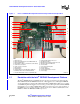
Intel® IXDP465 Development Platform—Quick Start Guide Figure 1. Photo of IXDP465 Development Platform Setup for Quick Start Operation 1 2 21 3 20 4 19 5 18 6 7 17 8 9 16 10 11 12 13 KEY: 1. Ethernet Port 0 2. Ethernet PHY Mezzanine Card in MII-0 NPE B slot 3. Ethernet SMII 6-pack 4. MII-1 NPE C location (no mezzanine card installed) 5. USB 2.0 Host Controller 6. USB 1.1 Device Controller 7. Flash Memory 8. DDRI Memory 9. UART1 Cable to PC for Wind River* VxWorks* 10.
Quick Start Guide—Intel® IXDP465 Development Platform Emulation is accomplished by accessing the EXP_UNIT_FUSE_RESET register via software and writing a 1 to the fuse bit number that corresponds to the feature to be disabled. For a full description of this register, see the Intel® IXP45X and Intel® IXP46X Product Line of Network Processors Developer’s Manual. Table 2 shows the default fuse bit settings for the fully-featured IXP465 network processor.
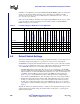
Intel® IXDP465 Development Platform—Quick Start Guide Table 3. Intel® IXDP465 Development Platform Switch Descriptions and Default Settings Board Location (See Figure 2) May 2005 10 Ref ID Switch Description Default Settings Quick Start Check? GPIO LED Switches SW1 Select individual LED illumination settings of all odd GPIO signals All odd GPIO illuminated. Switch in ON position.
Quick Start Guide—Intel® IXDP465 Development Platform Figure 2.
Intel® IXDP465 Development Platform—Quick Start Guide 7.0 Default Jumper Settings This section defines the factory default settings for all IXDP465 development platform jumpers, to ensure they were not accidentally changed during transport, or repositioned by a previous user of the platform.
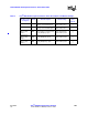
Quick Start Guide—Intel® IXDP465 Development Platform Table 4. Intel® IXDP465 Baseboard Jumper Descriptions and Default Settings (Sheet 2 of 2) Board Location (See Figure 3) MII/SMII/UTOPIA: ETH B MII/SMII/UTOPIA: ETH C MII/SMII/UTOPIA AN Ref ID JP4 JP65 JP95 JP9 JP11 Jumper Description for Installed State Connects ETH B-specific shared NPE signals to the NPE B mezzanine card Default Settings Installed. Connects ETH C-specific shared NPE signals to the NPE C mezzanine card Installed.
Intel® IXDP465 Development Platform—Quick Start Guide Figure 3.
Quick Start Guide—Intel® IXDP465 Development Platform 7.2 Intel® IXP465 Network Processor/DDR Module Jumpers Figure 4 identifies the jumper locations and Table 5 describes the jumper settings for the Intel® IXP465 Network Processor/DDR module. Table 5. Intel® IXP465 Network Processor/DDR Module Jumper Descriptions and Default Settings Board Location (See Figure 4) SCL P4 Jumper Description for Installed State Selects I2C pin, instead of GPIO Default Settings Quick Start Check? Shunt 1-2.
Intel® IXDP465 Development Platform—Quick Start Guide I2C IXP Intel® IXP465 Network Processor/DDR Module Jumper Locations GPIO Figure 4. SCL - P4 SDA - P2 IXP 3.3V XTAL OUT XTAL IN BYP SSCLK (installed by default) REFCLK SSCLK EN SSCLK JP46 IXP 2.
Quick Start Guide—Intel® IXDP465 Development Platform 7.3 Intel® IXPETM465 Ethernet PHY Mezzanine Card Jumpers Figure 5 identifies the jumper locations and Table 6 describes the jumper settings for the Ethernet card. Table 6. Intel® IXPETM465 Ethernet PHY Mezzanine Card Jumper Descriptions and Default Settings Board Location (See Figure 5) AN Jumper Description for Installed State Ref ID Default Settings Quick Start Check? GND JP1 GND Not installed. F GND JP3 GND Not installed.
Intel® IXDP465 Development Platform—Quick Start Guide Figure 5. Intel® IXPETM465 Ethernet PHY Mezzanine Card Jumper Locations !! "# ! 8.0 LCD Display and LED Indicators This section provides an overview of the LCD display, and also defines the locations, colors, and definitions of all LEDs, so that they can be visually monitored for proper power-up and booting.
Quick Start Guide—Intel® IXDP465 Development Platform Figure 6 on page 20 shows the exact locations for all LEDs on the IXDP465 development platform, per the descriptions and colors summarized in Table 7. Table 7.
Intel® IXDP465 Development Platform—Quick Start Guide Figure 6. Intel® IXDP465 Development Platform LED Locations +12.0V +5.0V -12.0V +1.5V +3.3V PCI Option COREV 2.5V 3.
Quick Start Guide—Intel® IXDP465 Development Platform 9.0 Preparing the Platform for Initial Use After unpacking the board and before powering on the board, the IXDP465 development platform needs to be prepared for first time use. To prepare the platform, follow these steps: 1. Verify that all default switch settings in Table 3 on page 10 are checked off. 2. Verify that all default jumper settings in Table 4 on page 12, Table 5 on page 15, and Table 6 on page 17 are checked off. 3.
Intel® IXDP465 Development Platform—Quick Start Guide 5. Verify the board booted properly by checking the LCD display • for RedBoot bootloader: line 1 = RedBoot line 2 = 0001 • for VxWorks bootloader: see Figure 7. Figure 7. LCD Display for Wind River* VxWorks* Bootloader 11.0 Operating the Platform The software release notes are intended to guide the user through software installation and setup of the host computer, and can be found at the following Web site: http://www.intel.