
Computer Hardware User Manual


4 Development Kit Manual
Document Number: 250807
Revision Number: 003
Revision Date: June 27, 2003
Contents
Figures
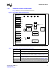
1Intel
®
IXD1110 Demo Board (Top View)............................................................... 9
2 Typical Test Setup ............................................................................................. 12
3Intel
®
IXF1110 CPU Daughter Card.................................................................... 13
4Intel
®
IXD1110 Demo Board Power (Revision A1) ............................................. 25
5Intel
®
IXD1110 Digital Power .............................................................................. 26
6Intel
®
IXD1110 Analog Power ............................................................................. 27
7Intel
®
IXD1110 Control........................................................................................ 28
8Intel
®
IXD1110 SerDes GBIC Ports 0-2 .............................................................. 29
9Intel
®
IXD1110 SerDes GBIC Ports 3-5 .............................................................. 30
10 Intel
®
IXD1110 SerDes GBIC Ports 6-8 .............................................................. 31
11 Intel
®
IXD1110 SerDes GBIC Port 9 ................................................................... 32
12 Intel
®
IXD1110 SPI4-2 ........................................................................................ 33
13 Intel
®
IXD1110 LEDs........................................................................................... 34
14 Intel
®
IXD1110 CPU Interface Control ................................................................ 35
15 Intel
®
IXD1110 CPU Connectors ........................................................................ 36
16 Intel
®
IXD1110 CPU Logic Probe Connectors .................................................... 37
Tables
1Intel
®
IXD1110 Demo Board Principal Components ............................................. 9
2 Pinout for DB-9–to–RJ-45 Connector ................................................................. 14
3 JTAG Test Signals (JP1)..................................................................................... 18
4 IXF1110 LED Behavior ....................................................................................... 19
5Intel
®
IXF1110 Reset Test Points ....................................................................... 20
6Intel
®
IXF1110 Differential Input Clock Test Points............................................. 20
7 GBIC Test Points ................................................................................................ 20
8 Mictor Connector Test Points.............................................................................. 21
9 Power Test Points ............................................................................................... 22
10 Ground Test Points ............................................................................................. 23
11 Unused Test Points............................................................................................. 24
12 Intel
®
IXD1110 Demo Board Bill of Materials (Rev. A1)...................................... 38