Intel® IXD1110 Demo Board Development Kit Manual June 2003 Document Number: 250807 Revision Number: 003 Revision Date: June 27, 2003
INFORMATION IN THIS DOCUMENT IS PROVIDED IN CONNECTION WITH INTEL® PRODUCTS. NO LICENSE, EXPRESS OR IMPLIED, BY ESTOPPEL OR OTHERWISE, TO ANY INTELLECTUAL PROPERTY RIGHTS IS GRANTED BY THIS DOCUMENT.
Contents Contents 1.0 Introduction......................................................................................................................... 7 1.1 1.2 1.3 2.0 About This Kit.....................................................................................................................7 Additional Equipment Required..........................................................................................7 About This Demo Board ..........................................................
Contents Figures 1 2 3 4 5 6 7 8 9 10 11 12 13 14 15 16 Intel® IXD1110 Demo Board (Top View)............................................................... 9 Typical Test Setup ............................................................................................. 12 Intel® IXF1110 CPU Daughter Card.................................................................... 13 Intel® IXD1110 Demo Board Power (Revision A1) ............................................. 25 Intel® IXD1110 Digital Power ........
Contents Revision History Revision 003 Rev. Date: June 27, 2003 Page # Description 11 Added second bullet under Section 2.0, “Quick Start”. 13 Modified Figure 3, “Intel® IXF1110 CPU Daughter Card”. 16 Added Section 5.3, “Changing the IP Address of the CPU Daughter Card (Optional)”. 18 Added note under Section 6.2, “JTAG Test Signals”. 18 Modified pin 8 description in Table 3, “JTAG Test Signals (JP1)”. 19 Modified Table 4, “IXF1110 LED Behavior”.
Contents 6 Development Kit Manual Document Number: 250807 Revision Number: 003 Revision Date: June 27, 2003
IXD1110 Demo Board 1.0 Introduction This document describes all the necessary requirements, settings, and procedures for evaluating the Intel® IXF1110 10-Port 1000 Mbps Ethernet Media Access Controller (MAC) using the Intel® IXD1110 demo board. For immediate operation, refer to Section 2.0, “Quick Start” on page 11. For optional configurations, see Section 6.0, “Optional Configurations” on page 18. The IXD1110 demo board kit includes a CPU daughter card that attaches to the underside of the board.
IXD1110 Demo Board 1.3 About The IXD1110 Demo Board The IXD1110 demo board provides a working platform for the evaluation of the IXF1110 in 1000 Mbps fiber optic applications. All ten network ports provide a 1000BASE-SX connection through the GBIC Small Form Factor Pluggable (SFP) modules (not included). The IXD1110 demo board contains one IXF1110 device, one SPI4-2 interface connector, ten GBIC SFP connectors, and one plug-in CPU daughter card.
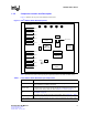
IXD1110 Demo Board 1.3.2 Component Location and Description Figure 1 illustrates the top view of the IXD1110 demo board. Figure 1. Intel® IXD1110 Demo Board (Top View) GBIC SFP Connectors GND 1.8GND V IXF 2.5 V IXF 3.3 V 2.
IXD1110 Demo Board Table 1. Intel® IXD1110 Demo Board Principal Components (Continued) Component Description S1 Reset Switch: This switch resets the entire board when pressed. SPI4-2 Interface Connector Allows a loopback connection when the loopback module is installed. This connector can also interface with alternate SPI4-2 connections. Mictor Connectors A, C, and D1 Provide access to selected IXF1110 signals. Refer to Section 8.4, “Mictor Connectors” on page 21 for more information.
IXD1110 Demo Board 2.0 Quick Start The quick-start procedure allows for IXF1110 1000 Mbps SerDes data transfer evaluation in the following interfaces: • IXF1110 SPI4-2 loopback data transfer • I2C signals • CPU interface 2.1 Setup The following quick-start procedure uses the IXIA* 1600T packet generator to evaluate the IXD1110 demo board. All ports on the IXF1110 are set to a default setting of 1000 Mbps full-duplex (see Figure 2, “Typical Test Setup” on page 12). 1.
IXD1110 Demo Board 3.0 Typical Test Setup Figure 2 shows a typical test setup for standard operation of the IXF1110 (see Section 2.0, “Quick Start” on page 11 for step-by-step details). The IXD1110 demo board can be connected to an IXIA* 1600T packet generator with LM1000SX cards for evaluation of the board. Each port can be connected to the IXIA* box with fiber cables. For IXF1110 software use, connect CAT5-UTP cables to the ports shown on the CPU daughter card.
IXD1110 Demo Board 4.0 CPU Daughter Card The IXD1110 demo board uses the Embedded Planet* RPX Classic LF (CLLF_BW31), a singleboard computer that uses the Motorola* MPC860 CPU. This card attaches to the underside of the board and is used to interface with the IXF1110 CPU interface. Figure 3 provides a top-level view of the CPU daughter card. Figure 3.
IXD1110 Demo Board For more information on the HyperTerminal and GUI interfaces, please refer to the IXF1110 Software Help File. 4.1 CPU FPGA The IXD1110 demo board has a Field Programmable Gate Array (FPGA) that allows the Motorola* CPU, which requires a synchronous interface, to interoperate with the asynchronous IXF1110 CPU interface. For additional information regarding the IXF1110 CPU interface, refer to the IXF1110 Datasheet. 4.
IXD1110 Demo Board 5.0 IXF1110 Software The IXF1110 software allows access to the following register blocks through the Graphical User Interface (GUI) or the Serial Monitor (HyperTerminal) interface: • • • • • • • • • MAC Control MAC RX Statistics MAC TX Statistics Global Status and Configuration RX Block TX Block SPI4-2 Block SerDes Block GBIC Block For additional information on all of the registers, please refer to the IXF1110 Datasheet or On-Line Help. Note: 5.
IXD1110 Demo Board 5.2 Installing the IXF1110 Software For proper installation of the IXF1110 software, follow these steps: 1. Verify that the CAT5-UTP cable is connected between the PC and the IXF1110 CPU daughter card. This allows access to the GUI interface. Refer to Section 4.0, “CPU Daughter Card” on page 13 for detailed installation instructions. 2.
IXD1110 Demo Board • Parity: None • Stops bits: 1 • Flow Control: None 3. Press the reset button switch SW1. The following message appears on the HyperTerminal: MPC8xx PlanetCore Boot Loader v2.00 Copyright 2001 Embedded Planet. All rights reserved. DRAM available size = 16 MB wvCV DRAM OK Autoboot in 2 seconds. ESC to abort, SPACE or ENTER to go. 4. Press the ESC key to stop the Autoboot. The following message appears on the HyperTerminal: Autoboot aborted. > 5.
IXD1110 Demo Board 6.0 Optional Configurations 6.1 Reset Jumper JP2 6.1.1 Standard Operation The Reset Jumper JP2 is required for standard operation of the IXD1110 demo board. Use the HRESET position for standard operation. The POR position is not recommended for standard operation of the IXD1110 demo board. This configuration only affects the CPU operation, and does not affect IXF1110 operation. The only difference between HRESET and POR is that POR also resets the CPU PLLs and state machines.
IXD1110 Demo Board 7.0 LEDs Table 4 describes the behavior of the Link LED - Amber, Link LED - Green, and Activity LED for the IXF1110. Table 4. IXF1110 LED Behavior Type RxLED Status Description Off Synchronization has occurred but no packets are being received and the Link LED Enable Register (Addr: 0x502) is not set. Amber On RX Synchronization has not occurred or no optical signal exists. Amber Blinking Port has remote fault and the LED Fault Disable Register (Addr: 0x50B) is not set.
IXD1110 Demo Board 8.0 Test Points 8.1 Reset Test Points Two test points allow evaluation of the IXF1110 reset signals. TP21 allows IXF1110 Sys_Res signal monitoring. DTP3 allows board reset signal monitoring. The board Sys_Res can be monitored on both test points if it is asserted by Switch S1 or the CPU. The reset is seen at TP21 if an IXF1110 reset is issued by the software interface. Table 5.
IXD1110 Demo Board Table 7. GBIC Test Points (Sheet 2 of 2) Test Point Symbol IXF1110 Ball Designator DTP11 I2C_DATA_4 E23 I2C_DATA_4 for IXF1110 DTP12 I2C_DATA_5 H24 I2C_DATA_5 for IXF1110 DTP13 I2C_DATA_6 G20 I2C_DATA_6 for IXF1110 2 Description DTP14 I C_DATA_7 E22 I2C_DATA_7 for IXF1110 DTP15 I2C_DATA_8 G24 I2C_DATA_8 for IXF1110 DTP16 I2C_DATA_9 F24 I2C_DATA_9 for IXF1110 NOTE: DTP = Differential Test Point 8.
IXD1110 Demo Board Table 8.
IXD1110 Demo Board Table 9. Power Test Points (Sheet 2 of 2) Test Point Symbol Description TP20 Vdd_3P3 3.3 V rest of the board TP22 TxAVTT_A SerDes Tx Block A 1.8 V TP23 TxAVTT_B SerDes Tx Block B 1.8 V TP24 RxAVTT_C SerDes Rx Block C 1.8 V TP25 RxA25_A SerDes Rx Block A 2.5 V TP26 RxAVTT_A SerDes Rx Block A 1.8 V TP27 TxA25_B SerDes Tx Block B 2.5 V TP28 RxA25_B SerDes Rx Block B 2.5 V TP29 RxAVTT_B SerDes Rx Block B 1.8 V TP30 TxAVTT_C SerDes Tx Block C 1.
IXD1110 Demo Board 8.6 Unused Test Points The unused test points are for internal testing only and are not designed for evaluation of the IXF1110 device. Table 11 provides a list of the unused test points. Table 11.
A B C D + 10uF C272 1 GND 5 C284 0.01uF Vdd_3P3 C285 0.01uF .001uF 0.1uF C287 0.01uF C283 C282 C286 0.01uF Vdd_3P3 Caps BANANA BN6 + C288 0.01uF 10uF C279 Vdd_3P3 - Digital 3.3V GND BANANA .001uF 0.1uF BN3 1 C278 C277 1 BANANA BN5 Vdd_2P5 - Digital 2.5V 1.0uF GND TP20 4 C290 0.01uF 1.0uF GND C289 0.01uF 100uF + C280 + C281 Vdd_3P3 100uF + C273 + C274 Vdd_2P5 TP19 1 C266 .001uF C265 0.1uF + 10uF C259 100uF GND BANANA BN4 1 3 0.1uF C275 .
A B C D GND 0 R1277 5 10K 10K R1273 R1271 GND C143 0.01uF GND Vdd_1P8_IXF C169 0.01uF Vdd_2P5_IXF 10K R1139 Vdd_1P8_IXF TP2 1 26 C172 0.01uF C173 0.01uF C174 0.01uF GND GND C4 D5 C144 0.01uF C145 0.01uF C147 0.01uF C148 0.01uF 4 C150 0.01uF R1269 R1267 C175 0.
5 GND TP9 GND 0.01uF C300 FB9 GND 0.01uF C308 FB13 GND 0.01uF C302 FB10 C142 0.01uF 0.01uF 4 GND 0.01uF 0.01uF TP30 0.01uF C315 TP29 0.01uF C303 TP23 0.01uF C309 TP26 0.01uF C301 TP22 C317 1 1 1 1 1 P3 V6 N3 P7 V15 V14 V10 V11 N22 P18 P22 V18 TP31 IXF1110 Analog Power 0.01uF C318 FB18 RxA25_C RxAVTT_C TxA25_C TxAVTT_C RxA25_B RxAVTT_B TxA25_B TxAVTT_B RxA25_A RxAVTT_A TxA25_A TxAVTT_A U1G 1 3 GND 0.
A B C D GND 13 11 9 8 10 SN74HC05 12 SN74HC05 U5F U5E 5 R16 0 IXF1110 uP_Rdy uP_Rd uP_Wr uP_Cs EP1K30TC144-1-IXF-FX IXF0_reset_n 4 138 4 reset_n R1141 10K Vdd_2P5 2 1 System Interface LED Interface JTAG Interface SN74LV08AD 1B 1A U23A Sys_Res CLK50 CLK125 LED_LATCH LED_CLK LED_DATA TDI TDO TMS TCLK TRST I2C_CLK TX_FAULT_Int TxPauseAdd0 TxPauseAdd1 TxPauseAdd2 TxPauseAdd3 TxPauseFr GBIC RX_LOS_Int Interface MOD_DEF_Int Pause Control TxPauseFR TxPauseAdd0 Tx
A B C D GND I2C_DATA_2 Port 2 GND I2C_DATA_1 Port 1 GND I2C_DATA_0 Port 0 5 DIFF TP + | DTP9 DIFF TP + | DTP8 DIFF TP + | DTP7 U1H I2C_CLK U1I IXF1110 SerDes/GBIC - Port 0 Document Number: 250807 Revision Number: 003 Revision Date: June 27, 2003 U1J IXF1110 SerDes/GBIC - Port 1 Development Kit Manual IXF1110 SerDes/GBIC - Port 2 2,4,5,6 I2C_CLK 5 Rx_Los2 MOD_DEF2 I2C_DATA_2 RxN2 RxP2 TxP2 TxN2 TX_Fault_2 TX_Disable_2 Rx_Los1 MOD_DEF1 I2C_DATA_1 RxN1 RxP1 TxP
A B C D GND I2C_DATA_5 Port 5 GND I2C_DATA_4 Port 4 GND I2C_DATA_3 Port 3 DIFF TP + | DTP12 DIFF TP + | DTP11 DIFF TP + | DTP10 5 5 U1K I2C_CLK U1L IXF1110 SerDes/GBIC - Port 3 U1M IXF1110 SerDes/GBIC - Port 4 30 IXF1110 SerDes/GBIC - Port 5 2,3,5,6 I2C_CLK Rx_Los5 MOD_DEF5 I2C_DATA_5 RxN5 RxP5 TxP5 TxN5 TX_Fault_5 TX_Disable_5 Rx_Los4 MOD_DEF4 I2C_DATA_4 RxN4 RxP4 TxP4 TxN4 TX_Fault_4 TX_Disable_4 Rx_Los3 MOD_DEF3 I2C_DATA_3 RxN3 RxP3 TxP3 TxN3 TX_Fa
A B C D GND I2C_DATA_8 Port 8 GND I2C_DATA_7 Port 7 GND I2C_DATA_6 Port 6 DIFF TP + | DTP15 DIFF TP + | DTP14 DIFF TP + | DTP13 5 U1N U1O IXF1110 U1P IXF1110 IXF1110 Rx_Los8 MOD_DEF8 I2C_DATA_8 RxN8 RxP8 TxP8 TxN8 TX_Fault_8 TX_Disable_8 Rx_Los7 MOD_DEF7 I2C_DATA_7 RxN7 RxP7 TxP7 TxN7 TX_Fault_7 TX_Disable_7 Rx_Los6 MOD_DEF6 I2C_DATA_6 RxN6 RxP6 TxP6 TxN6 TX_Fault_6 TX_Disable_6 I2C_CLK SerDes/GBIC - Port 6 Document Number: 250807 Revision Number: 003 R
A B C D GND I2C_DATA_9 Port 9 DIFF TP + | DTP16 5 5 U1Q IXF1110 SerDes/GBIC - Port 9 2,3,4,5 I2C_CLK Rx_Los9 MOD_DEF9 I2C_DATA_9 RxN9 RxP9 TxP9 TxN9 TX_Fault_9 TX_Disable_9 I2C_CLK P2 L1 F24 X Rx_Los9 I2C_DATA_9 I2C_CLK Mod_Def9 RxN9 4 7 8 4 5 6 12 13 Y5 18 19 2 3 RxP9 X TxP9 TxN9 4.7k R88 Y6 4.7k R87 T5 U5 4.7k 4.
Document Number: 250807 Revision Number: 003 Revision Date: June 27, 2003 A B 5 U1C IXF1110 SPI-4 Phase 2 - RX Development Kit Manual C D 5 RSClk RSTAT1 RSTAT0 RDClk_P RDClk_N RCTL_P RCTL_N RDat_P_0 RDat_N_0 RDat_P_1 RDat_N_1 RDat_P_2 RDat_N_2 RDat_P_3 RDat_N_3 RDat_P_4 RDat_N_4 RDat_P_5 RDat_N_5 RDat_P_6 RDat_N_6 RDat_P_7 RDat_N_7 RDat_P_8 RDat_N_8 RDat_P_9 RDat_N_9 RDat_P_10 RDat_N_10 RDat_P_11 RDat_N_11 RDat_P_12 RDat_N_12 RDat_P_13 RDat_N_13 RDat_P_14 RDat_N_14 RDat_P_15 RD
A B C D reset_n GND 10pF 10pF GND 5 10pF C297 10pF 22 C296 GND 12 13 LED_LATCH 22 11 10 R366 14 LED2_DATA_0 LED_CLK reset_n GND C293 C292 R365 GND 22 GND 12 13 LED_LATCH R362 11 10 LED_CLK reset_n 22 R361 14 LED_DATA 2 LED_LATCH 2,9 2 LED_CLK 2 LED_DATA 5 QH QA QB QC QD QE QF QG QH QH QA QB QC QD QE QF QG QH MM74HC595M RCLK G SRCLK SRCLR SER U12 MM74HC595M RCLK G SRCLK SRCLR SER U10 LED_LATCH reset_n LED_CLK LED_DATA 9 15 1 2 3 4 5 6 7 9
A B C D uPx_WrN 2,11 2,11 2,11 2,11 TxPauseAdd0 TxPauseAdd1 TxPauseAdd2 TxPauseAdd3 2,11 TxPauseFR uPx_CsN 2,11 2,11 uPx_RdN GND uPx_RdyN 2,11 2,11 1K R1265 Vdd_3P3 2 3 4 5 TP1 50 50 50 50 R227 R228 R229 R230 TxPauseAdd0 TxPauseAdd1 TxPauseAdd2 TxPauseAdd3 5 1 GND 50 R226 TxPauseFR I2C_CLK_OUT 50 50 R224 uPx_CsN R378 50 R223 uPx_WrN J25 SMB 50 R222 GND uPx_RdN R360 10K 1K R1264 Vdd_3P3 nCONFIG CONF_DONE nSTATUS DCLK DATA0 10K R220 Vdd_3P3 uPx_RdyN 1 140
A B C D 2,11 POR 5 5 GND B60 B59 B58 B57 B56 B55 B54 B53 B52 B51 B50 B49 B48 B47 B46 B45 B44 B43 B42 B41 B40 B39 B38 B37 B36 B35 B34 B33 B32 B31 B30 B29 B28 B27 B26 B25 B24 B23 B22 B21 B20 B19 B18 B17 B16 B15 B14 B13 B12 B11 B10 B9 B8 B7 B6 B5 B4 B3 B2 B1 AMP_179031-5_P2 GND POR A0 GND A2 A1 A4 A3 A6 A5 AT0/MII_CRS A7 AT1/MII_MDIO DP0/IRQ3 DP2/IRQ5 DP1/IRQ4 DP3/IRQ6 AT2/MII_TXEN IRQ0 AT3/MII_COL IRQ2 IRQ1 GND IRQ3 PE0 GND GND PD15 PD14 GND GND PD13 PD12 GND GND PD11 PD10 GND GND PD9 PD8 GND G
A B BUS_CLK Bus_Busy Bus_Request Bus_Grant CsN GenP_CsN RD/~WR Start_XFER TA 1 2 3 4 5 6 7 8 9 10 11 12 13 14 15 16 17 18 19 BUS_CLK uPx_Data31 uPx_Data30 uPx_Data29 uPx_Data28 uPx_Data27 uPx_Data26 uPx_Data25 uPx_Data24 uPx_Data23 uPx_Data22 uPx_Data21 uPx_Data20 uPx_Data19 uPx_Data18 uPx_Data17 uPx_Data16 IRQ uPx_Add10 uPx_Add9 uPx_Add8 uPx_Add7 uPx_Add6 uPx_Add5 uPx_Add4 uPx_Add3 uPx_Add2 uPx_Add1 uPx_Add0 uPx_Data15 uPx_Data14 uPx_Data13 uPx_Data12 uPx_Data11 uPx_Data10 uPx_Data9 uPx_Data8 uPx
IXD1110 Demo Board 10.0 Bill of Materials Table 12. Intel® IXD1110 Demo Board Bill of Materials (Rev. A1) Reference Designator Manufacturer1 Description Part Number BN1, 3-6 CONN BANANA NUT SILVER EF Johnson 108-0740-001 C1-2, 122-132, 134, 136-138, 140-145, 147-148, 150-153, 155-157, 162-166, 168-194, 300-319 CAP .
IXD1110 Demo Board Table 12. Intel® IXD1110 Demo Board Bill of Materials (Rev.
IXD1110 Demo Board Table 12. Intel® IXD1110 Demo Board Bill of Materials (Rev. A1) (Continued) Reference Designator Manufacturer1 Description Part Number TP2-17, 19-21 TESTPOINT SILVER LOOP (SMD) Components Corp. (Lab stock-reel) TP-108-02 U1 IC MAC IXF1110 10 PORT Intel IXF1110 U3 OSC 125 MHZ 3.3V 4 PIN SMD Pletronics SM7744DSV-125.0M U4 OSC 50.0 MHZ 3.3V 4 PIN SMD Pletronics SM7744HSV-50.