® Intel ISP1100 Internet Server Product Guide A Guide for Technically Qualified Assemblers of Intel® Identified Subassemblies/Products Order Number: A10528-001
Disclaimer Intel Corporation (Intel) makes no warranty of any kind with regard to this material, including, but not limited to, the implied warranties of merchantability and fitness for a particular purpose. Intel assumes no responsibility for any errors that may appear in this document. Intel makes no commitment to update nor to keep current the information contained in this document. No part of this document may be copied or reproduced in any form or by any means without prior written consent of Intel.
Contents 1 Description System Components ............................................................................................................ 7 Server Board Features ......................................................................................................... 8 Server Board Connectors and Components ......................................................................... 9 Controls, Connectors, and Indicators...............................................................................
Installing the Processor ...................................................................................................... 28 Removing the Processor Fan (If Applicable) .............................................................. 29 Installing the Processor Chip ..................................................................................... 30 Installing the Processor Heat Sink ............................................................................. 31 Removing the DIMM Boards.............
After the System Has Been Running Correctly ................................................................... 69 Checklist .................................................................................................................... 69 More Problem Solving Procedures ..................................................................................... 70 Preparing the System for Diagnostic Testing ............................................................. 70 Monitoring POST .....................
25. 26. 27. 28. 29. Installing the Add-in Card(s) on the Riser .................................................................. 46 Removing the Rear I/O Filler Panel(s) ....................................................................... 47 Installing the Riser and Add-in Card(s) ...................................................................... 48 Replacing the Lithium Back-up Battery ...................................................................... 50 Powering Up the Server.................
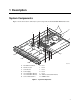
1 Description System Components Figure 1 shows the location of the major system components in the Intel® ISP1100 Internet Server. A B M I J C D N G F K L E H A. PCI Add-in Card Slots H. B. PCI Riser Card I. Fan 2 C. Server Board J. Fan 3 Fan 1 D. Power Supply K. Fan 4 E. 1-Inch Hard Drive Bracket L. Fan 5 F. 1-Inch Hard Drive Bracket M. Add-In Card Retention Bracket G. 3.5-Inch Diskette Drive OMO9445 N. DIMM Sockets Figure 1.
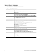
Server Board Features Table 1 summarizes the TR440BX server board features. Table 1. Server Board Features Feature Description Form Factor MicroATX (9.6 inches by 9.6 inches) Processor Supports an Intel® Pentium® III processor or Intel Celeron™ processor in a PGA370 socket.
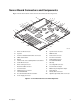
Server Board Connectors and Components Figure 2 shows the locations of the server board connectors and components. AA A B C Z T U V W X D E Y F G H I S R Q J K P L O M N A. Wake on LAN Connector OMO9446 O. System Fans Connectors B. Speaker P. DIMM Sockets C. PCI Riser Sideband and PCI Bus Connectors Q. Front Panel Connector D. SMSC I/O Controller R. Front Panel Controller E. Battery S. Primary IDE Connector F. Intel Pro/100+ Server (82559) Ethernet Controllers T.
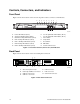
Controls, Connectors, and Indicators Front Panel Figure 3 shows the locations of the server front-panel controls, connectors, and indicators. A B C D E F G H M N J K I L OMO9447 A. Power LED Indicator (Green) H. User-Programmable LED Indicator (Green) B. System Fault LED Indicator (Amber) I. User-Programmable LED Indicator (Green) C. Hard Drive Activity LED Indicator (Green) J. Power Switch D. LAN 1 Activity LED Indicator (Yellow) K. Sleep Switch E.
Processors The server board supports a single Intel Pentium III processor or Celeron processor that plugs into a PGA370 socket connector that secures the processor chip with a zero-insertion-force (ZIF) arm. The host bus speed (66 MHz or 100 MHz) is automatically selected. Table 2 lists the processors supported by the server board. Table 2.
• • Unbuffered DIMMs of the following sizes: 16 MB, 32 MB, 64 MB, 128 MB and 256 MB for a total memory size of 1 GB. Registered DIMMs of the following sizes: 64MB, 128Mb and 256MB for a maximum memory size of 1 GB. Only non-stacked DIMMs are supported because of a server board space constraint. Table 3.
NOTE All memory components used with the server board should comply with the following PC SDRAM specifications (see Chapter 13 in the Intel® ISP1100 Internet Server Technical Product Specification for information about how to obtain these specifications): • • • PC SDRAM Specification (memory component specific) PC Unbuffered SDRAM Specifications PC Serial Presence Detection Specification Processors with 100 MHz host bus speed must be paired only with 100 MHz SDRAM.
IDE Support The server board has two independent bus-mastering IDE interfaces that support: 1. ATAPI devices (such as CD-ROM drives). 2. ATA devices using the transfer modes listed in the Intel ISP1100 Internet Server Technical Product Specification. The BIOS supports logical block addressing (LBA) and extended cylinder head sector (ECHS) translation modes. The drive reports the transfer rate and translation mode to the BIOS.
I/O Controller The FDC37B807 I/O controller from SMSC is an ISA Plug and Play-compatible, multifunctional I/O device that provides the following features (see Chapter 13 in the Intel ISP1100 Internet Server Technical Product Specification for Plug and Play specification information): • • • • • Two serial ports. Interface for one 1.2 MB, 1.44 MB, or 2.88 MB diskette drive. Three-mode diskette drive support (driver required). FIFO support on both serial and diskette drive interfaces.
Keyboard and Mouse Interface The PS/2 keyboard and mouse connectors are located on the server back panel. The +5 V lines to these connectors are protected with a PolySwitch† circuit that, like a self-healing fuse, reestablishes the connection after an overcurrent condition is removed. The keyboard controller contains the AMI keyboard and mouse controller code, provides the keyboard and mouse control functions, and supports password protection for power on/reset.
For more details on programming and reading the Heceta 2 chip please refer to the Heceta 2 Device Specification version 1.2 or later (see Chapter 13 in the Intel ISP1100 Internet Server Technical Product Specification for how to obtain this specification). SCSI Hard Drive LED Connector The optional SCSI hard drive LED connector is a 1 x 2-pin connector that allows add-in SCSI controller applications to use the same LED as the IDE controller.
Wake on Ring/Resume on Ring Wake on Ring enables the computer to wake from sleep or soft-off mode when a call is received on a telephony device, such as a faxmodem. The server board provides three methods for implementing Wake on Ring: 1. An external modem connected to Serial Port A (rear) can toggle the super I/O controller’s Ring Indicator pin which should be enabled to cause a wakeup event. 2. The 2-pin Wake on Ring header may be shorted to cause a wakeup event. 3.
SMI and NMI Routing There are numerous SMI sources and all are routed to the PIIX4. Software must configure the PIIX4 SMI source pins to control whether SMI is propagated through to the processor via its H_SMI input or not. For details on the fault conditions that cause SMI to occur, consult the data sheets of the SMI source ICs. The SMI routing on the server board is described in Table 6. Note that some PIIX4 inputs have several sources. Schematic signal names are in parenthesis. Table 6.
Fan Support The server board has five fan connectors. The functions of the fan connectors are described in Table 7. Table 7. 20 Fan Connector Descriptions Connector Function Fan 1 (J35) Supports fan speed sensing for fans with tachometer outputs. Connector supports variable fan speed. Fan 2 (J34) Supports fan speed sensing for fans with tachometer outputs. Connector supports variable fan speed. Fan 3 (J33) Supports fan speed sensing for fans with tachometer outputs.
2 Removing/Installing Server Components This chapter provides procedures for removing and installing replaceable and/or upgradable components in the Intel ISP1100 Internet Server. Before performing the procedures, be sure to familiarize yourself with the following “Before You Begin” information.
WARNINGS This chapter is intended for qualified technical personnel with experience installing and configuring servers. SYSTEM POWER ON/OFF: The Power button on the server front panel DOES NOT remove AC power to the server system. Some circuitry in the server may continue to operate even though the front panel Power button is off. Always disconnect the power cord from the AC power source or wall outlet before performing any of the procedures in this guide.
Rackmount Precautions Familiarize yourself with the following precautions before rackmounting the server. WARNINGS ANCHOR THE EQUIPMENT RACK: The equipment rack must be anchored to an unmovable support to prevent it from falling over when one or more devices are extended in front of it on slide assemblies. The anchors must be able to withstand a force of up to 113 kg (250 lbs.). You must also consider the weight of any other device installed in the rack.
Safety and Regulatory Requirements This product was evaluated for use in computer racks within computer rooms and similar locations. Other uses require further evaluation. Safety Compliance rd rd USA/Canada UL 1950, 3 Edition/CSA 22.2, No.
Installing the Server in the Rack This procedure describes how to install the server in the rack. Before proceeding, be sure and familiarize yourself with the “Rackmount Precautions” information in the “Before You Begin” section at the front of this chapter. Refer to Figure 5 while performing this procedure. 1. Orient the server with the rackmount brackets aligned with the desired mounting holes (A) in the rack posts (B). 2.
Removing the Cover This procedure describes how to remove the cover from the server. Before proceeding, be sure you are thoroughly familiar with the information in “Before You Begin” at the front of this chapter. Refer to Figure 6 while performing this procedure. 1. Use a Phillips screwdriver and remove the screw (A) from the front edge of the cover. 2.
Removing the Processor This procedure describes how to remove the processor on the server board. Before proceeding, be sure you are thoroughly familiar with the information in “Before You Begin” at the front of this chapter. WARNING If the server has been running recently, the processor chip, heat sink, and adjacent components will be hot. To avoid burns, allow time for the processor chip, heat sink, and adjacent components to cool before you proceed with these procedures.
Removing the Processor Chip Perform this procedure to remove the processor chip from the socket. Refer to Figure 8 while performing this procedure. 1. Face the front of the server and grasp the end of the zero-insertion-force (ZIF) arm (A) on the left side of the processor socket. 2. Bend the ZIF arm slightly to the left until it disengages from the socket tab (B). 3. Swing the arm up until it stops in the straight up position. The processor chip is now loose in the socket. 4.
Removing the Processor Fan (If Applicable) This procedure describes how to remove the processor fan from a replacement processor. Due to space constraints, the server will not accommodate a processor with a fan mounted on the heat sink. Sufficient cooling is provided in the server without the processor fan. If the processor you wish to install has a fan mounted on top of the heat sink, remove the fan as described in the following procedure. Otherwise, proceed to “Installing the Processor Chip.
Installing the Processor Chip Perform this procedure to install the processor chip in the socket. Refer to Figure 10 while performing this procedure. 1. Grasp the end of the zero-insertion-force (ZIF) arm (A) and bend it out slightly until it disengages from the socket tab (B). 2. Swing the ZIF arm up until it stops in the straight up position. The processor socket is now unlocked. 3.
Installing the Processor Heat Sink Perform this procedure to install the heat sink on the processor chip. Refer to Figure 11 while performing this procedure. 1. Orient the heat sink so the thermal grease pad (A) on the heat sink is exactly aligned with the corresponding thermal grease pad (B) on top of the processor chip. 2. With the end of the clamp that has the two slots (C) facing the front of the socket, drop the clamp in the bottom of the heat sink center groove (D). 3.
Removing the DIMM Boards This procedure describes how to remove DIMM boards from the server board sockets. Before proceeding, be sure you are thoroughly familiar with the information in “Before You Begin” at the front of this chapter. Refer to Figure 12 while performing this procedure. 1. Grasp the ejector lever (A) on one end of the DIMM board and push down on the lever until the end of the board edge connector (B) just lifts out of the server board socket (C).
Installing the DIMM Boards This procedure describes how to install DIMM boards on the server board. Before proceeding, be sure you are thoroughly familiar with the information in “Before You Begin” at the front of this chapter. Refer to Figure 13 while performing this procedure. CAUTIONS Make sure that the DIMM board(s) you wish to install has the appropriate characteristics. See Chapter 1 for the required characteristics of the supported memory. Use extreme care when installing a DIMM board.
Removing the Hard Drive(s) This procedure describes how to remove the hard drives from the server drive bays. Before proceeding, be sure you are thoroughly familiar with the information in “Before You Begin” at the front of this chapter. Refer to Figure 14 while performing this procedure. 1. Disconnect the power and data cables (A) from the back of the drive. 2. Grasp the back of the drive and lift until the drive mounting bracket (B) releases from the two snaptop standoffs (C). 3.
Installing the Hard Drive(s) This procedure describes how to install hard drives in the server drive bays. Before proceeding, be sure you are thoroughly familiar with the information in “Before You Begin” at the front of this chapter. Installing the Hard Drive in the Mounting Bracket Perform this procedure to install the hard drive in the mounting bracket. Refer to Figure 15 while performing this procedure.
Installing the Hard Drive in the Drive Bay Perform this procedure to install the mounting bracket with the hard drive in the drive bay. Refer to Figure 16 while performing this procedure. 1. Connect the power and data cables to the back of the drive (D). 2. Position the drive in the server drive bay so that the end of the bracket with the tabs (A) is facing the server front panel. 3. Gently guide the bracket tabs into the mating slots (B) in the server front panel. 4.
Removing the 3.5-inch Diskette Drive This procedure describes how to remove the 3.5-inch diskette drive from the server drive bay. Before proceeding, be sure you are thoroughly familiar with the information in “Before You Begin” at the front of this chapter. Refer to Figure 17 while performing this procedure. 1. Disconnect the power and data cables (A) from the back of the drive. 2.
Installing the 3.5-inch Diskette Drive This procedure describes how to install the 3.5-inch diskette drive in the server drive bay. Before proceeding, be sure you are thoroughly familiar with the information in “Before You Begin” at the front of this chapter. Installing the Drive in the Mounting Bracket Perform this procedure to install the 3.5-inch diskette drive in the mounting bracket. Refer to Figure 18 while performing this procedure.
Installing the 3.5-inch Diskette Drive in the Drive Bay Perform this procedure to install the mounting bracket and drive in the server drive bay. Refer to Figure 19 while performing this procedure. 1. Connect the power and data cables (C) to the drive. The red stripe (D) on the data cable faces toward the center of the drive. 2.
Removing the PCI Add-in Card(s) This procedure describes how to remove the PCI add-in card(s) from the server board. Before proceeding, be sure you are thoroughly familiar with the information in “Before You Begin” at the front of this chapter. Removing the Filler Panel Retention Bracket Perform this procedure to remove the filler panel retention bracket from the server back panel. Refer to Figure 20 while performing this procedure. 1.
Removing the Riser and Add-in Card(s) Perform this procedure to remove the riser and add-in card(s) from the server board. Refer to Figure 21 while performing this procedure. CAUTION Do not attempt to remove an add-in card without first removing the riser card from the server board. If you do, you can damage the board(s) or connectors due to clearance limitations.
Removing the Add-in Card(s) From the Riser Perform this procedure to remove the add-in card(s) from the riser card. Refer to Figure 22 while performing this procedure. 1. Grasp the edges of the riser card and the add-in card you wish to remove. 2. Firmly hold the riser card while gently rocking and pulling the add-in card until the add-in card releases from the riser connector. 3. Remove the add-in card from the riser connector. OMO9460 Figure 22.
Installing the Rear I/O Filler Panel(s) CAUTION Be sure any empty expansion slot(s) have a filler panel installed as described in the following “Installing the Rear I/O Filler Panel(s)” procedure. An open expansion slot reduces the cooling and EMI integrity of the server and can effect performance and/or cause damage due to overheating. NOTE Perform this procedure only if you are not immediately reinstalling another add-in card in the same expansion slot from which an add-in card was removed.
Installing PCI Add-in Card(s) This procedure describes how to install the PCI add-in card(s) in the server expansion slots. The vertically mounted riser card accommodates one standard (left side) and one low-profile (right side) PCI add-in card. Before proceeding, be sure you are thoroughly familiar with the information in “Before You Begin” at the front of this chapter.
Removing/Installing Server Components 45
Installing the Add-in Card(s) on the Riser Perform this procedure to install the standard or low-profile add-in cards on the riser card. Refer to Figure 25 while performing this procedure. Before you begin, examine the length of the bracket at the end of the add-in card you wish to install to determine whether it is a standard or a low-profile type. The low-profile card bracket is shorter than the standard card; approximately 3.11 in. (7.9 cm) compared to approximately 4.75 in. (12.06 cm) long.
Removing the Rear I/O Filler Panel(s) NOTE Perform this procedure only if you are installing PCI add-in card(s) in unused expansion slots that still have an I/O filler panel installed. Perform this procedure to remove the rear I/O filler panel(s). Refer to Figure 26 while performing this procedure. 1. Use a Phillips screwdriver and remove the two screws (A) securing the filler panel retention bracket (B) to the top edge of the server back panel. 2. Remove the retention bracket. 3.
Installing the Riser and Add-in Card(s) Perform this procedure to install the riser and add-in card(s) in the server PCI expansion slots. Refer to Figure 27 while performing this procedure. 1. Align the riser card edge connector (A) with the mating riser connector on the server board. (The connectors are keyed to mate in only one direction.
Replacing the Back-up Battery This procedure describes how to remove and replace the lithium battery on the server board. The lithium battery powers the real-time clock (RTC) in the absence of AC power. The lithium battery lasts for up to 10 years; but when it starts to lose voltage the server settings stored in the CMOS RAM in the RTC (for example, the date and time) may be incorrect. Contact your supplier or dealer for a list of approved devices.
1. Remove the server cover as described in the “Removing the Server Cover” procedure. 2. Insert the tip of a flat bladed screwdriver (A), or equivalent, under the tab in the plastic battery retainer (B). 3. Gently push down on the screwdriver to lift the battery (C). 4. Remove the battery from the socket. WARNING 5. 6. 7. 8. 9. Replace the lithium battery only with the same or equivalent type recommended by the dealer.
Power Up the Server This procedure describes how to apply AC power and power up the server (refer to Figure 29). Before proceeding, be sure you are thoroughly familiar with the “Before You Begin” information at the front of this guide. WARNING Carefully check the AC power cord. If it is not the exact type required in the region where the server will be installed and used, replace the cord with the correct type. Refer to the following “Power Cord Requirements” for a detailed power cord description.
1. Attach the female end of the appropriate AC power cord to the mating AC power receptacle on the server back panel. 2. Plug the male end of the AC power cord into the AC power source (wall outlet). 3. Open the bezel door (A) to access the Power switch (C) as follows: a. Grasp the tab (B) at each end of the hinged bezel door. b. Gently pull the tabs out and down to swing open the hinged bezel door. 4.
Removing/Installing Server Components 53
3 Configuration Software and Utilities This chapter describes the Power-On Self-Test (POST) and server configuration utilities. The table below briefly describes the utilities. Table 8. Configuration Utilities Utility Description and brief procedure Page BIOS Setup The BIOS Setup program is for viewing and changing BIOS settings for the server. 55 BIOS Update Utility Use to update the BIOS or recover from a corrupted BIOS update.
Note the screen display and write down the beep code you hear; this information is useful for your service representative. For a listing of beep codes and error messages that POST can generate, see the “Solving Problems” chapter in this manual. Using BIOS Setup The Setup program is used for viewing and changing the BIOS settings of this system. The user accesses Setup by pressing key after the POST memory test begins and before the operating system boot begins.
Table 11. BIOS Setup Function Keys (continued) Description Setup Key <↑> or <↓> Select Item: The up or down arrow selects the previous or next value in a pick list, or the previous or next feature in a menu item’s option list. The selected item must then be activated by pressing the key. <→> or <←> Select Menu: The left and right arrow keys move between the major menu pages. The keys have no effect if a sub-menu or pick list is displayed.
Advanced Menu The menu bar is shown below. Advanced Main Security Boot System Management Exit Table 13 shows the Advanced menu. This menu configures advanced features that are available through the chipset. Table 13. Feature Advanced Menu Options Description Boot Configuration See Table 14 Configures Plug and Play, Numlock key, and reset Configuration Data on next boot. Peripheral Configuration See Table 15 Configures peripheral ports and devices.
Table 16. IDE Configuration Menu Feature Options Description IDE Controller Boot (default) “Disabled” disables the integrated IDE Controller. “Primary” enables only the primary IDE Controller. “Secondary” enables the secondary IDE Controller. “Both” enables both IDE Controllers. Disabled Primary Secondary Hard Disk Pre-Delay Disabled (default) 3 seconds Selects the hard disk drive pre-delay. Causes the BIOS to insert a delay before attempting to detect IDE drives in the system.
Table 17. IDE Configuration Submenu (continued) Feature Options Description PIO Mode Auto (default) Configures the PIO mode. 0 1 2 3 4 Ultra DMA Disabled (default) Configures the Ultra DMA mode. Mode 0 Mode 1 Mode 2 Mode 3 Mode 4 Table 18. Diskette Configuration Submenu Feature Options Description Diskette Controller Disabled Disables or enables the integrated diskette controller. Floppy A Not Installed Enabled (default) Disables or enables serial port B. 360KB 5.25” 1.2MB 5.
Security Menu The menu bar is shown below. Main Advanced System Management Boot Security Exit Table 20 shows the Security menu. This menu sets passwords and security features. Table 20. Security Menu Feature Options Description User Password Is No options Displays whether or not there is a supervisor password installed. Default is no user password installed. Supervisor Password Is No options Displays whether or not there is a user password installed.
Table 21. Boot Menu (continued) Feature Options Description After Power Failure Stays Off Determines the mode of operation if a power loss occurs. “Stays Off” keeps system off once power is restored. “Power On” boots the system after power is restored. “Last State” restores the system to the same state it was in before the power failed.
System Management Menu The menu bar is shown below. Main Advanced Security System Management Boot Exit Table 22 shows the System Management menu. This menu sets server management features. Table 22. System Management Menu Feature Options Description Serial Port Disabled Configures which COM port to use for serial console redirection. COM1 3F8 IRQ4 (default) COM2 2F8 IRQ3 COM3 3E8 IRQ4 Serial Console Redirection Disabled Baud Rate 9600 Disables or enables serial console redirection.
Exit Menu The menu bar is shown below. Main Advanced Security Boot System Management Exit Table 23 shows the Exit menu. This menu exits the Setup program – saving, discarding, and loading default settings. Table 23. Exit Menu Feature Options Description Exit Saving Changes No options Exits system Setup and saves your changes in CMOS. Exit Discarding Changes No options Exits system setup without saving your changes in CMOS. Load Setup Defaults No options Loads setup defaults.
Obtaining the Upgrade Utility You can upgrade to a new version of the BIOS using the new BIOS files and the BIOS upgrade utility, iFLASH.EXE. You can obtain the BIOS upgrade file and the iFLASH.EXE utility through your computer supplier or from the Intel Customer Support website: http://www.intel.com/isp NOTE Please review the instructions distributed with the upgrade utility before attempting a BIOS upgrade. This upgrade utility allows you to: • • Upgrade the BIOS in flash memory.
7. To extract the BIOS.EXE file to the floppy disk, change to the temporary directory that holds the BIOS.EXE file and type: BIOS A: 8. Press . 9. The floppy disk now holds the BIOS upgrade and recovery files. Performing the Upgrade 1. 2. 3. 4. 5. Boot the computer with the floppy disk in drive A. The BIOS upgrade utility screen appears. Select Update Flash Memory From a File. Select Update System BIOS. Press . Use the arrow keys to select the correct .bio file. Press .
8. 9. 10. 11. Two beeps and the end of activity in drive A indicate successful BIOS recovery. A series of continuous beeps indicates failed BIOS recovery. If recovery fails, return to step 1 and repeat the recovery process. If recovery is successful, turn off the computer. Remove the computer cover and continue with the following steps. 12. Set the BIOS configuration jumper to pins 1-2. 13. Replace the computer cover. Leave the upgrade disk in drive A and turn on the computer. 14.
Configuration Software and Utilities 67
4 Solving Problems This chapter helps you identify and solve problems that might occur while you are using the system. Resetting the System To do this: Press: Soft boot reset, which clears system memory and reloads the operating system. Clear system memory, restart POST, and reload the operating system. Reset button Cold boot reset. Turn the system power off and then on. This clears system memory, restarts POST, reloads the operating system, and halts power to all peripherals.
Running New Application Software Problems that occur when you run new application software are usually related to the software. Faulty equipment is much less likely, especially if other software runs correctly. Checklist q Does the system meet the minimum hardware requirements for the software? See the software documentation. q Is the software an authorized copy? If not, get one; unauthorized copies often do not work.
More Problem Solving Procedures This section provides a more detailed approach to identifying a problem and locating its source. Preparing the System for Diagnostic Testing CAUTION Turn off devices before disconnecting cables: Before disconnecting any peripheral cables from the system, turn off the system and any external peripheral devices. Failure to do so can cause permanent damage to the system and/or the peripheral devices. 1. Turn off the system and all external peripheral devices.
Specific Problems and Corrective Actions This section provides possible solutions for these specific problems: • • • • • • • • • • Power light does not light. There is no beep or an incorrect beep pattern. No characters appear on screen. Characters on the screen appear distorted or incorrect. System cooling fans do not rotate. Diskette drive activity light does not light. Hard disk drive activity light does not light. CD-ROM drive activity light does not light. There are problems with application software.
4. If you do not receive a beep code and characters do not appear, the video display monitor or video controller may have failed. Contact your service representative or authorized dealer for help. Characters Are Distorted or Incorrect Check the following: q Are the brightness and contrast controls properly adjusted on the video monitor? See the manufacturer’s documentation.
Hard Disk Drive Activity Light Does Not Light If you have installed one or more hard disk drives in your system, check the following: q Are the power and signal cables to the drive properly installed? q Are all relevant switches and jumpers on the hard drive and adapter board set correctly? q Is the onboard IDE controller enabled? (IDE hard drives only) q Is the hard disk drive properly configured? NOTE Front panel hard disk LED indicates IDE and SCSI devices: The hard disk drive activity light on the fron
q Check the network controller LEDs that are visible through an opening at the system back panel. Problems with Network The server hangs when the drivers are loaded. q Change the PCI BIOS interrupt settings. Try the “PCI Installation Tips” below. Diagnostics pass, but the connection fails. q Make sure the network cable is securely attached. q Make sure you specify the correct frame type in your NET.CFG file. The Link LED doesn’t light. q Make sure you have loaded the network drivers.
q If other software runs correctly on the system, contact your vendor about the failing software. If the problem persists, contact the software vendor’s customer service representative for help. Bootable CD-ROM Is Not Detected Check the following: q Is the BIOS set to allow the CD-ROM to be the first bootable device? Error and Informational Messages When you turn on the system, POST displays messages that provide information about the system.
Table 25. Error Messages Description Error Message Description 8042 Gate-A20 Error Gate A20 on the keyboard controller (8042) is not working. Replace the 8042. Address Line Short! Error in the address decoding circuitry. C: Drive Error No response from drive C:. Run the AMIDiag Hard Disk Utility. Check the C: hard disk type in Standard Setup. C: Drive Failure No response from hard disk drive C:. Replace the drive. Cache Memory Bad, Do Not Enable Cache! Cache memory is defective. Run AMIDiag.
Table 25. Error Messages Description (continued) Error Message Description No ROM BASIC Cannot find a proper bootable sector on drive A:, C:, or CD-ROM drive. AMIBIOS cannot find ROM Basic. Parity error in memory installed on an adapter card in an expansion slot. The format is: Off Board Parity Error OFF BOARD PARITY ERROR ADDR = (XXXX) XXXX is the hex address where the error occurred. Run AMIDiag to find and correct memory problems. Parity error in serverboard memory.
Index A add-in cards installation, 44, 47 installation on riser, 45 removal, 40 audible beep error codes, 53 B battery, 14 disposing of safely, 48 replacement, 48 beep codes, 53 BIOS recovering, 64 upgrading, 54, 62 BIOS update utility, 53 bootable media, required by POST, 53 booting cold, 67 C Caution DIMM types, matching, 33 DIMMs, use extreme care when installing, 33 ESD protection, 22 installing chassis covers for cooling and airflow, 22 selecting correct processor, 28 chipset, 13 IDE support, 14 real
I I/O controller, 15 diskette drive controller, 15 keyboard and mouse interface, 16 serial ports, 15 IDE support, 14 indicators, 10 K-L keyboard and mouse interface, 16 keyboard interface, 16 LED connector, 17 lithium backup battery disposing of safely, 48 replacement, 48 network, 73 no characters on screen, 70 power light, 70 preparing system for diagnostic testing, 69 random error in data files, 68 screen characters incorrect, 71 system cooling fans do not rotate, 71 system lights, 69 processor installa
removing/installing server components (continued) removing the PCI add-in cards, 40 removing the processor, 27 removing the processor chip, 28 removing the processor fan, 29 removing the processor heat sink, 27 removing the rear I/O filler panels, 46 removing the riser and add-in cards, 41 removing the riser card, 44 replacing cover, 26 replacing the backup battery, 48 safety and regulatory requirements, 24 safety compliance, 24 tools needed, 24 warnings and cautions, 21 reset system, 53, 67 resume on ring,
Index 81