BX400ii Interposer Board User’s Manual March 29, 2000 Order Number: 273224-003
Information in this document is provided in connection with Intel products. No license, express or implied, by estoppel or otherwise, to any intellectual property rights is granted by this document.
BX400ii Interposer Board Contents 1.0 Introduction......................................................................................................................... 5 1.1 1.2 1.3 1.4 1.5 2.0 Getting Started ................................................................................................................... 9 2.1 2.2 3.0 Key Terms ............................................................................................................. 5 Related Documents.......................
1.0 Introduction This document introduces the BX400ii Interposer Board and provides installation instructions. The BX400ii Interposer Board with the Intel® Mobile Pentium® II Processor emulates the functionality of the Intel® Pentium® II Processor Mobile Module to provide a bus interconnect for emulation and logic analysis tools. This board is used for Intel Pentium II Processor Mobile Module system designs. Note: 1.
Introduction 1.3 Pentium® II Processor Mobile Module: Mobile Module Connector 2 or Low Power Pentium II Processor Module The Pentium II Processor Mobile Module: Mobile Module Connector 2 (400-pin MMC-2) or Low Power Pentium II Processor Module (LPM) is a small, highly integrated assembly containing an Intel Pentium II processor and its immediate system-level support.
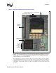
Introduction Figure 1. Top View of BX400ii Interposer Board Assembly Mobile Pentium® II Processor in Minicartridge 30-Pin Debug Port Connector 190-Pin System Bus Connector 82443BX Host Bridge Controller Dashed line indicates 400-Pin LPM Connector on underside A6366-01 The same 400-pin system interface is still provided to allow connection to the target system. In addition, a top side 240-pin connection is added for the Intel Mobile Pentium II Processor in minicartridge.
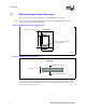
Introduction 1.5 BX400ii Interposer Board Dimensions This section provides the physical dimensions for the BX400ii Interposer Board. Note: Notice in Figure 2 the mechanical clearance requirements for the BX400ii Interposer Board compared to the Low Power Module (LPM). Figure 2. BX400ii Keepout Space Requirements Top View 190-Pin Connector BX-400ii 4" 5.25" LPM 400-Pin Connector on the LPM (Low Power Module) 2.5" 4" A6372-01 Figure 3.
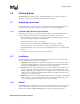
Getting Started 2.0 Getting Started The BX400ii Interposer Board requires a Mobile Pentium II Processor in mini-cartridge at a frequency corresponding to the mobile module that is being emulated. 2.1 Unpacking Instructions Carefully unpack the contents of the box and verify that all of the items in the packing list are present. If items are missing or damaged, contact Intel or your authorized distributor. 2.1.
Getting Started Note: 2.2.2 Please consider the thermal requirements of your Mobile Pentium II processor and ensure that the proper thermal management solution is in place. Emulator/Logic Analyzer Connect the 30-pin cable from the emulator or logic analyzer to the debug port connector on the BX400ii Interposer Board. If you have a debug port designed into your system, only the debug port on the BX400ii Interposer Board will function.
Hardware Reference 3.0 Hardware Reference For a hardware layout of the BX400ii Interposer Board, refer to Figure 5 on page 13. For board dimensions and keepout space requirements, refer to Figure 2 and Figure 3 on page 8. 3.1 Connector Definitions Changes to the hardware are not required for the BX400ii Interposer Board.
Hardware Reference 3.3 Test Points Power measurement header descriptions are provided in Table 4. Table 4. 12 Power Measurement Header Descriptions Header Voltage Rail Resistor Effective Resistance (Ω) P1 +VGTLREF_BX (5/9 VTT) R28 0.01 GTL reference voltage for 440BX P2 +V3_AGPREF (3.3V) R45 0.01 3.3 V rail for 440BX AGPset: 82443BX reference P5, P6 +V3_BX (3.3V) R57 0.01 3.3 V rail for BX core P7 +V3_PU (3.3V) R58 0.01 3.3 V rail for pull-ups P8 +V3_VR (3.3V) R59 0.01 3.
Hardware Reference Figure 5.