
Desktop 4th Generation Specification Sheet

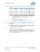
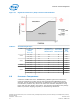
Table Of Contents
- Contents
- Revision History
- 1.0 Introduction
- 2.0 Interfaces
- 3.0 Technologies
- 3.1 Intel® Virtualization Technology (Intel® VT)
- 3.2 Intel® Trusted Execution Technology (Intel® TXT)
- 3.3 Intel® Hyper-Threading Technology (Intel® HT Technology)
- 3.4 Intel® Turbo Boost Technology 2.0
- 3.5 Intel® Advanced Vector Extensions 2.0 (Intel® AVX2)
- 3.6 Intel® Advanced Encryption Standard New Instructions (Intel® AES-NI)
- 3.7 Intel® Transactional Synchronization Extensions - New Instructions (Intel® TSX-NI)
- 3.8 Intel® 64 Architecture x2APIC
- 3.9 Power Aware Interrupt Routing (PAIR)
- 3.10 Execute Disable Bit
- 3.11 Supervisor Mode Execution Protection (SMEP)
- 4.0 Power Management
- 4.1 Advanced Configuration and Power Interface (ACPI) States Supported
- 4.2 Processor Core Power Management
- 4.3 Integrated Memory Controller (IMC) Power Management
- 4.4 PCI Express* Power Management
- 4.5 Direct Media Interface (DMI) Power Management
- 4.6 Graphics Power Management
- 5.0 Thermal Management
- 5.1 Desktop Processor Thermal Profiles
- 5.2 Thermal Metrology
- 5.3 Fan Speed Control Scheme with Digital Thermal Sensor (DTS) 1.1
- 5.4 Fan Speed Control Scheme with Digital Thermal Sensor (DTS) 2.0
- 5.5 Processor Temperature
- 5.6 Adaptive Thermal Monitor
- 5.7 THERMTRIP# Signal
- 5.8 Digital Thermal Sensor
- 5.9 Intel® Turbo Boost Technology Thermal Considerations
- 6.0 Signal Description
- 6.1 System Memory Interface Signals
- 6.2 Memory Reference and Compensation Signals
- 6.3 Reset and Miscellaneous Signals
- 6.4 PCI Express*-Based Interface Signals
- 6.5 Display Interface Signals
- 6.6 Direct Media Interface (DMI)
- 6.7 Phase Locked Loop (PLL) Signals
- 6.8 Testability Signals
- 6.9 Error and Thermal Protection Signals
- 6.10 Power Sequencing Signals
- 6.11 Processor Power Signals
- 6.12 Sense Signals
- 6.13 Ground and Non-Critical to Function (NCTF) Signals
- 6.14 Processor Internal Pull-Up / Pull-Down Terminations
- 7.0 Electrical Specifications
- 8.0 Package Mechanical Specifications
- 9.0 Processor Ball and Signal Information

• Uncharacterized workloads may exist that could result in higher turbo frequencies
and power. If that were to happen, the processor Thermal Control Circuitry (TCC)
would protect the processor. The TCC protection must be enabled by the platform
for the product to be within specification.
An illustration of Intel Turbo Boost Technology power control is shown in the following
sections and figures. Multiple controls operate simultaneously allowing for
customization for multiple system thermal and power limitations. These controls
provide turbo optimizations within system constraints.
Package Power Control
The package power control allows for customization to implement optimal turbo within
platform power delivery and package thermal solution limitations.
Table 28. Intel
®
Turbo Boost Technology 2.0 Package Power Control Settings
MSR:
Address:
MSR_TURBO_POWER_LIMIT
610h
Control Bit Default Description
POWER_LIMIT_1 (PL1) 14:0 SKU TDP
• This value sets the average power limit over a long time
period. This is normally aligned to the TDP of the part and
steady-state cooling capability of the thermal solution. The
default value is the TDP for the SKU.
• PL1 limit may be set lower than TDP in real time for specific
needs, such as responding to a thermal event. If it is set
lower than TDP, the processor may require to use frequencies
below the guaranteed P1 frequency to control the low-power
limits. The PL1 Clamp bit [16] should be set to enable the
processor to use frequencies below P1 to control the set-
power limit.
• PL1 limit may be set higher than TDP. If set higher than TDP,
the processor could stay at that power level continuously and
cooling solution improvements may be required.
POWER_LIMIT_1_TIME
(Turbo Time Parameter)
23:17 1 sec
This value is a time parameter that adjusts the algorithm
behavior to maintain time averaged power at or below PL1. The
hardware default value is 1 second; however, 28 seconds is
recommended for most mobile applications.
POWER_LIMIT_2 (PL2) 46:32 1.25 x TDP
PL2 establishes the upper power limit of turbo operation above
TDP, primarily for platform power supply considerations. Power
may exceed this limit for up to 10 ms. The default for this limit is
1.25 x TDP; however, the BIOS may reprogram the default value
to maximize the performance within platform power supply
considerations. Setting this limit to TDP will limit the processor to
only operate up to the TDP. It does not disable turbo because
turbo is opportunistic and power/temperature dependent. Many
workloads will allow some turbo frequencies for powers at or
below TDP.
5.9.2
Processor—Thermal Management
Desktop 4th Generation Intel
®
Core
™
Processor Family, Desktop Intel
®
Pentium
®
Processor Family, and Desktop Intel
®
Celeron
®
Processor Family
Datasheet – Volume 1 of 2 December 2013
80 Order No.: 328897-004