
Desktop 4th Generation Specification Sheet

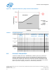
Table Of Contents
- Contents
- Revision History
- 1.0 Introduction
- 2.0 Interfaces
- 3.0 Technologies
- 3.1 Intel® Virtualization Technology (Intel® VT)
- 3.2 Intel® Trusted Execution Technology (Intel® TXT)
- 3.3 Intel® Hyper-Threading Technology (Intel® HT Technology)
- 3.4 Intel® Turbo Boost Technology 2.0
- 3.5 Intel® Advanced Vector Extensions 2.0 (Intel® AVX2)
- 3.6 Intel® Advanced Encryption Standard New Instructions (Intel® AES-NI)
- 3.7 Intel® Transactional Synchronization Extensions - New Instructions (Intel® TSX-NI)
- 3.8 Intel® 64 Architecture x2APIC
- 3.9 Power Aware Interrupt Routing (PAIR)
- 3.10 Execute Disable Bit
- 3.11 Supervisor Mode Execution Protection (SMEP)
- 4.0 Power Management
- 4.1 Advanced Configuration and Power Interface (ACPI) States Supported
- 4.2 Processor Core Power Management
- 4.3 Integrated Memory Controller (IMC) Power Management
- 4.4 PCI Express* Power Management
- 4.5 Direct Media Interface (DMI) Power Management
- 4.6 Graphics Power Management
- 5.0 Thermal Management
- 5.1 Desktop Processor Thermal Profiles
- 5.2 Thermal Metrology
- 5.3 Fan Speed Control Scheme with Digital Thermal Sensor (DTS) 1.1
- 5.4 Fan Speed Control Scheme with Digital Thermal Sensor (DTS) 2.0
- 5.5 Processor Temperature
- 5.6 Adaptive Thermal Monitor
- 5.7 THERMTRIP# Signal
- 5.8 Digital Thermal Sensor
- 5.9 Intel® Turbo Boost Technology Thermal Considerations
- 6.0 Signal Description
- 6.1 System Memory Interface Signals
- 6.2 Memory Reference and Compensation Signals
- 6.3 Reset and Miscellaneous Signals
- 6.4 PCI Express*-Based Interface Signals
- 6.5 Display Interface Signals
- 6.6 Direct Media Interface (DMI)
- 6.7 Phase Locked Loop (PLL) Signals
- 6.8 Testability Signals
- 6.9 Error and Thermal Protection Signals
- 6.10 Power Sequencing Signals
- 6.11 Processor Power Signals
- 6.12 Sense Signals
- 6.13 Ground and Non-Critical to Function (NCTF) Signals
- 6.14 Processor Internal Pull-Up / Pull-Down Terminations
- 7.0 Electrical Specifications
- 8.0 Package Mechanical Specifications
- 9.0 Processor Ball and Signal Information

Adaptive Thermal Monitor
The Adaptive Thermal Monitor feature provides an enhanced method for controlling
the processor temperature when the processor silicon exceeds the Thermal Control
Circuit (TCC) activation temperature. Adaptive Thermal Monitor uses TCC activation to
reduce processor power using a combination of methods. The first method (Frequency
control, similar to Thermal Monitor 2 (TM2) in previous generation processors)
involves the processor reducing its operating frequency (using the core ratio
multiplier) and internal core voltage. This combination of lower frequency and core
voltage results in a reduction of the processor power consumption. The second
method (clock modulation, known as Thermal Monitor 1 or TM1 in previous generation
processors) reduces power consumption by modulating (starting and stopping) the
internal processor core clocks. The processor intelligently selects the appropriate TCC
method to use on a dynamic basis. BIOS is not required to select a specific method
(as with previous-generation processors supporting TM1 or TM2). The temperature at
which Adaptive Thermal Monitor activates the Thermal Control Circuit is factory
calibrated and is not user configurable. Snooping and interrupt processing are
performed in the normal manner while the TCC is active.
When the TCC activation temperature is reached, the processor will initiate TM2 in
attempt to reduce its temperature. If TM2 is unable to reduce the processor
temperature, TM1 will be also be activated. TM1 and TM2 will work together (clocks
will be modulated at the lowest frequency ratio) to reduce power dissipation and
temperature.
With a properly designed and characterized thermal solution, it is anticipated that the
TCC will only be activated for very short periods of time when running the most power
intensive applications. The processor performance impact due to these brief periods of
TCC activation is expected to be so minor that it would be immeasurable. An under-
designed thermal solution that is not able to prevent excessive activation of the TCC in
the anticipated ambient environment may cause a noticeable performance loss, and in
some cases may result in a T
CASE
that exceeds the specified maximum temperature
and may affect the long-term reliability of the processor. In addition, a thermal
solution that is significantly under designed may not be capable of cooling the
processor even when the TCC is active continuously. See the appropriate processor
Thermal Mechanical Design Guidelines for information on designing a compliant
thermal solution.
The Thermal Monitor does not require any additional hardware, software drivers, or
interrupt handling routines. The following sections provide more details on the
different TCC mechanisms used by the processor.
Frequency Control
When the Digital Temperature Sensor (DTS) reaches a value of 0 (DTS temperatures
reported using PECI may not equal zero when PROCHOT# is activated), the TCC will
be activated and the PROCHOT# signal will be asserted if configured as bi-directional.
This indicates the processor temperature has met or exceeded the factory calibrated
trip temperature and it will take action to reduce the temperature.
Upon activation of the TCC, the processor will stop the core clocks, reduce the core
ratio multiplier by 1 ratio and restart the clocks. All processor activity stops during this
frequency transition that occurs within 2 us. Once the clocks have been restarted at
the new lower frequency, processor activity resumes while the core voltage is reduced
by the internal voltage regulator. Running the processor at the lower frequency and
voltage will reduce power consumption and should allow the processor to cool off. If
5.6
Thermal Management—Processor
Desktop 4th Generation Intel
®
Core
™
Processor Family, Desktop Intel
®
Pentium
®
Processor Family, and Desktop Intel
®
Celeron
®
Processor Family
December 2013 Datasheet – Volume 1 of 2
Order No.: 328897-004 75