
Desktop 4th Generation Specification Sheet
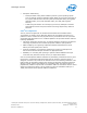

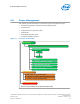
Table Of Contents
- Contents
- Revision History
- 1.0 Introduction
- 2.0 Interfaces
- 3.0 Technologies
- 3.1 Intel® Virtualization Technology (Intel® VT)
- 3.2 Intel® Trusted Execution Technology (Intel® TXT)
- 3.3 Intel® Hyper-Threading Technology (Intel® HT Technology)
- 3.4 Intel® Turbo Boost Technology 2.0
- 3.5 Intel® Advanced Vector Extensions 2.0 (Intel® AVX2)
- 3.6 Intel® Advanced Encryption Standard New Instructions (Intel® AES-NI)
- 3.7 Intel® Transactional Synchronization Extensions - New Instructions (Intel® TSX-NI)
- 3.8 Intel® 64 Architecture x2APIC
- 3.9 Power Aware Interrupt Routing (PAIR)
- 3.10 Execute Disable Bit
- 3.11 Supervisor Mode Execution Protection (SMEP)
- 4.0 Power Management
- 4.1 Advanced Configuration and Power Interface (ACPI) States Supported
- 4.2 Processor Core Power Management
- 4.3 Integrated Memory Controller (IMC) Power Management
- 4.4 PCI Express* Power Management
- 4.5 Direct Media Interface (DMI) Power Management
- 4.6 Graphics Power Management
- 5.0 Thermal Management
- 5.1 Desktop Processor Thermal Profiles
- 5.2 Thermal Metrology
- 5.3 Fan Speed Control Scheme with Digital Thermal Sensor (DTS) 1.1
- 5.4 Fan Speed Control Scheme with Digital Thermal Sensor (DTS) 2.0
- 5.5 Processor Temperature
- 5.6 Adaptive Thermal Monitor
- 5.7 THERMTRIP# Signal
- 5.8 Digital Thermal Sensor
- 5.9 Intel® Turbo Boost Technology Thermal Considerations
- 6.0 Signal Description
- 6.1 System Memory Interface Signals
- 6.2 Memory Reference and Compensation Signals
- 6.3 Reset and Miscellaneous Signals
- 6.4 PCI Express*-Based Interface Signals
- 6.5 Display Interface Signals
- 6.6 Direct Media Interface (DMI)
- 6.7 Phase Locked Loop (PLL) Signals
- 6.8 Testability Signals
- 6.9 Error and Thermal Protection Signals
- 6.10 Power Sequencing Signals
- 6.11 Processor Power Signals
- 6.12 Sense Signals
- 6.13 Ground and Non-Critical to Function (NCTF) Signals
- 6.14 Processor Internal Pull-Up / Pull-Down Terminations
- 7.0 Electrical Specifications
- 8.0 Package Mechanical Specifications
- 9.0 Processor Ball and Signal Information
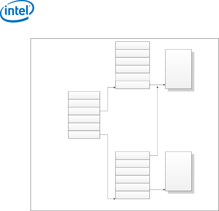
Figure 10. Device to Domain Mapping Structures
Root entry 0
Root entry N
Root entry 255
Context entry 0
Context entry 255
Context entry 0
Context entry 255
(Bus 255)
(Bus N)
(Bus 0)
Root entry table
(Dev 31, Func 7)
(Dev 0, Func 1)
(Dev 0, Func 0)
Context entry Table
For bus N
Context entry Table
For bus 0
Address Translation
Structures for Domain A
Address Translation
Structures for Domain B
Intel VT-d functionality, often referred to as an Intel VT-d Engine, has typically been
implemented at or near a PCI Express host bridge component of a computer system.
This might be in a chipset component or in the PCI Express functionality of a processor
with integrated I/O. When one such Intel VT-d engine receives a PCI Express
transaction from a PCI Express bus, it uses the B/D/F number associated with the
transaction to search for an Intel VT-d translation table. In doing so, it uses the B/D/F
number to traverse the data structure shown in the above figure. If it finds a valid
Intel VT-d table in this data structure, it uses that table to translate the address
provided on the PCI Express bus. If it does not find a valid translation table for a given
translation, this results in an Intel VT-d fault. If Intel VT-d translation is required, the
Intel VT-d engine performs an N-level table walk.
For more information, refer to Intel
®
Virtualization Technology for Directed I/O
Architecture Specification http://download.intel.com/technology/computing/vptech/
Intel(r)_VT_for_Direct_IO.pdf
Intel
®
VT-d Features
The processor supports the following Intel VT-d features:
Processor—Technologies
Desktop 4th Generation Intel
®
Core
™
Processor Family, Desktop Intel
®
Pentium
®
Processor Family, and Desktop Intel
®
Celeron
®
Processor Family
Datasheet – Volume 1 of 2 December 2013
42 Order No.: 328897-004