
Desktop 4th Generation Specification Sheet
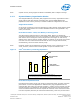
Table Of Contents
- Contents
- Revision History
- 1.0 Introduction
- 2.0 Interfaces
- 3.0 Technologies
- 3.1 Intel® Virtualization Technology (Intel® VT)
- 3.2 Intel® Trusted Execution Technology (Intel® TXT)
- 3.3 Intel® Hyper-Threading Technology (Intel® HT Technology)
- 3.4 Intel® Turbo Boost Technology 2.0
- 3.5 Intel® Advanced Vector Extensions 2.0 (Intel® AVX2)
- 3.6 Intel® Advanced Encryption Standard New Instructions (Intel® AES-NI)
- 3.7 Intel® Transactional Synchronization Extensions - New Instructions (Intel® TSX-NI)
- 3.8 Intel® 64 Architecture x2APIC
- 3.9 Power Aware Interrupt Routing (PAIR)
- 3.10 Execute Disable Bit
- 3.11 Supervisor Mode Execution Protection (SMEP)
- 4.0 Power Management
- 4.1 Advanced Configuration and Power Interface (ACPI) States Supported
- 4.2 Processor Core Power Management
- 4.3 Integrated Memory Controller (IMC) Power Management
- 4.4 PCI Express* Power Management
- 4.5 Direct Media Interface (DMI) Power Management
- 4.6 Graphics Power Management
- 5.0 Thermal Management
- 5.1 Desktop Processor Thermal Profiles
- 5.2 Thermal Metrology
- 5.3 Fan Speed Control Scheme with Digital Thermal Sensor (DTS) 1.1
- 5.4 Fan Speed Control Scheme with Digital Thermal Sensor (DTS) 2.0
- 5.5 Processor Temperature
- 5.6 Adaptive Thermal Monitor
- 5.7 THERMTRIP# Signal
- 5.8 Digital Thermal Sensor
- 5.9 Intel® Turbo Boost Technology Thermal Considerations
- 6.0 Signal Description
- 6.1 System Memory Interface Signals
- 6.2 Memory Reference and Compensation Signals
- 6.3 Reset and Miscellaneous Signals
- 6.4 PCI Express*-Based Interface Signals
- 6.5 Display Interface Signals
- 6.6 Direct Media Interface (DMI)
- 6.7 Phase Locked Loop (PLL) Signals
- 6.8 Testability Signals
- 6.9 Error and Thermal Protection Signals
- 6.10 Power Sequencing Signals
- 6.11 Processor Power Signals
- 6.12 Sense Signals
- 6.13 Ground and Non-Critical to Function (NCTF) Signals
- 6.14 Processor Internal Pull-Up / Pull-Down Terminations
- 7.0 Electrical Specifications
- 8.0 Package Mechanical Specifications
- 9.0 Processor Ball and Signal Information

• PCI Express* extended configuration space. The first 256 bytes of configuration
space aliases directly to the PCI Compatibility configuration space. The remaining
portion of the fixed 4-KB block of memory-mapped space above that (starting at
100h) is known as extended configuration space.
• PCI Express* Enhanced Access Mechanism. Accessing the device configuration
space in a flat memory mapped fashion.
• Automatic discovery, negotiation, and training of link out of reset.
• Traditional AGP style traffic (asynchronous non-snooped, PCI-X Relaxed ordering).
• Peer segment destination posted write traffic (no peer-to-peer read traffic) in
Virtual Channel 0: DMI -> PCI Express* Port 0
• 64-bit downstream address format, but the processor never generates an address
above 64 GB (Bits 63:36 will always be zeros).
• 64-bit upstream address format, but the processor responds to upstream read
transactions to addresses above 64 GB (addresses where any of Bits 63:36 are
nonzero) with an Unsupported Request response. Upstream write transactions to
addresses above 64 GB will be dropped.
• Re-issues Configuration cycles that have been previously completed with the
Configuration Retry status.
• PCI Express* reference clock is 100-MHz differential clock.
• Power Management Event (PME) functions.
• Dynamic width capability.
• Message Signaled Interrupt (MSI and MSI-X) messages.
• Polarity inversion
Note: The processor does not support PCI Express* Hot-Plug.
PCI Express* Architecture
Compatibility with the PCI addressing model is maintained to ensure that all existing
applications and drivers operate unchanged.
The PCI Express* configuration uses standard mechanisms as defined in the PCI Plug-
and-Play specification. The processor PCI Express* ports support Gen 3. At 8 GT/s,
Gen 3 operation results in twice as much bandwidth per lane as compared to Gen 2
operation. The 16 lanes PEG can operate at 2.5 GT/s, 5 GT/s, or 8 GT/s.
Gen 3 PCI Express* uses a 128b/130b encoding that is about 23% more efficient than
the 8b/10b encoding used in Gen 1 and Gen 2.
The PCI Express* architecture is specified in three layers – Transaction Layer, Data
Link Layer, and Physical Layer. See the PCI Express Base Specification 3.0 for details
of PCI Express* architecture.
PCI Express* Configuration Mechanism
The PCI Express* (external graphics) link is mapped through a PCI-to-PCI bridge
structure.
2.2.2
2.2.3
Processor—Interfaces
Desktop 4th Generation Intel
®
Core
™
Processor Family, Desktop Intel
®
Pentium
®
Processor Family, and Desktop Intel
®
Celeron
®
Processor Family
Datasheet – Volume 1 of 2 December 2013
24 Order No.: 328897-004