
Desktop 4th Generation Specification Sheet
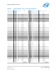
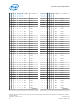
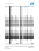
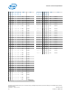
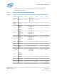
Table Of Contents
- Contents
- Revision History
- 1.0 Introduction
- 2.0 Interfaces
- 3.0 Technologies
- 3.1 Intel® Virtualization Technology (Intel® VT)
- 3.2 Intel® Trusted Execution Technology (Intel® TXT)
- 3.3 Intel® Hyper-Threading Technology (Intel® HT Technology)
- 3.4 Intel® Turbo Boost Technology 2.0
- 3.5 Intel® Advanced Vector Extensions 2.0 (Intel® AVX2)
- 3.6 Intel® Advanced Encryption Standard New Instructions (Intel® AES-NI)
- 3.7 Intel® Transactional Synchronization Extensions - New Instructions (Intel® TSX-NI)
- 3.8 Intel® 64 Architecture x2APIC
- 3.9 Power Aware Interrupt Routing (PAIR)
- 3.10 Execute Disable Bit
- 3.11 Supervisor Mode Execution Protection (SMEP)
- 4.0 Power Management
- 4.1 Advanced Configuration and Power Interface (ACPI) States Supported
- 4.2 Processor Core Power Management
- 4.3 Integrated Memory Controller (IMC) Power Management
- 4.4 PCI Express* Power Management
- 4.5 Direct Media Interface (DMI) Power Management
- 4.6 Graphics Power Management
- 5.0 Thermal Management
- 5.1 Desktop Processor Thermal Profiles
- 5.2 Thermal Metrology
- 5.3 Fan Speed Control Scheme with Digital Thermal Sensor (DTS) 1.1
- 5.4 Fan Speed Control Scheme with Digital Thermal Sensor (DTS) 2.0
- 5.5 Processor Temperature
- 5.6 Adaptive Thermal Monitor
- 5.7 THERMTRIP# Signal
- 5.8 Digital Thermal Sensor
- 5.9 Intel® Turbo Boost Technology Thermal Considerations
- 6.0 Signal Description
- 6.1 System Memory Interface Signals
- 6.2 Memory Reference and Compensation Signals
- 6.3 Reset and Miscellaneous Signals
- 6.4 PCI Express*-Based Interface Signals
- 6.5 Display Interface Signals
- 6.6 Direct Media Interface (DMI)
- 6.7 Phase Locked Loop (PLL) Signals
- 6.8 Testability Signals
- 6.9 Error and Thermal Protection Signals
- 6.10 Power Sequencing Signals
- 6.11 Processor Power Signals
- 6.12 Sense Signals
- 6.13 Ground and Non-Critical to Function (NCTF) Signals
- 6.14 Processor Internal Pull-Up / Pull-Down Terminations
- 7.0 Electrical Specifications
- 8.0 Package Mechanical Specifications
- 9.0 Processor Ball and Signal Information
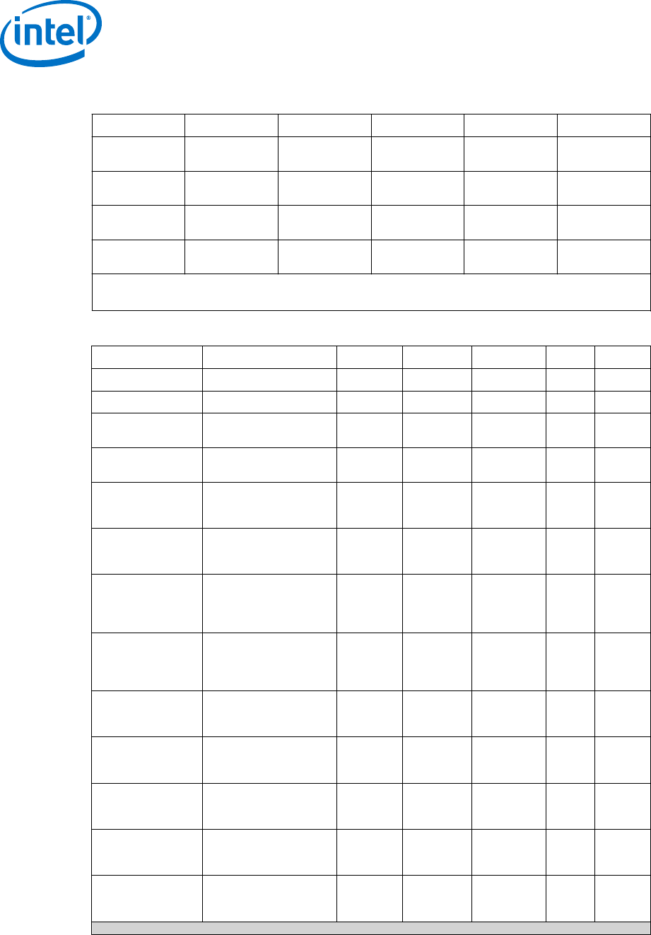
Table 49. VCCIO_OUT, VCOMP_OUT, and VCCIO_TERM
Symbol Parameter Typ Max Units Notes
VCCIO_OUT
Termination
Voltage
1.0 — V
ICCIO_OUT
Maximum
External Load
— 300 mA
VCOMP_OUT
Termination
Voltage
1.0 — V 1
VCCIO_TERM
Termination
Voltage
1.0 — V 2
Notes: 1. VCOMP_OUT may only be used to connect to PEG_RCOMP and DP_RCOMP.
2. Internal processor power for signal termination.
Table 50. DDR3 / DDR3L Signal Group DC Specifications
Symbol Parameter Min Typ Max Units Notes
1
V
IL
Input Low Voltage — V
DDQ
/2 0.43*V
DDQ
V 2, 4, 11
V
IH
Input High Voltage 0.57*V
DDQ
V
DDQ
/2 — V 3, 11
V
IL
Input Low Voltage
(SM_DRAMPWROK)
— — 0.15*V
DDQ
V —
V
IH
Input High Voltage
(SM_DRAMPWROK)
0.45*V
DDQ
— 1.0 V 10, 12
R
ON_UP(DQ)
DDR3/DDR3L Data
Buffer pull-up
Resistance
20 26 32 Ω 5, 11
R
ON_DN(DQ)
DDR3/DDR3L Data
Buffer pull-down
Resistance
20 26 32 Ω 5, 11
R
ODT(DQ)
DDR3/DDR3L On-die
termination equivalent
resistance for data
signals
38
50 62 Ω 11
V
ODT(DC)
DDR3/DDR3L On-die
termination DC working
point (driver set to
receive mode)
0.45*V
DDQ
0.5*V
DDQ
0.55*V
DDQ
V 11
R
ON_UP(CK)
DDR3/DDR3L Clock
Buffer pull-up
Resistance
20 26 32 Ω
5, 11,
13
R
ON_DN(CK)
DDR3/DDR3L Clock
Buffer pull-down
Resistance
20 26 32 Ω
5, 11,
13
R
ON_UP(CMD)
DDR3/DDR3L Command
Buffer pull-up
Resistance
15 20 25 Ω
5, 11,
13
R
ON_DN(CMD)
DDR3/DDR3L Command
Buffer pull-down
Resistance
15 20 25 Ω
5, 11,
13
R
ON_UP(CTL)
DDR3/DDR3L Control
Buffer pull-up
Resistance
19 25 31 Ω
5, 11,
13
continued...
Processor—Electrical Specifications
Desktop 4th Generation Intel
®
Core
™
Processor Family, Desktop Intel
®
Pentium
®
Processor Family, and Desktop Intel
®
Celeron
®
Processor Family
Datasheet – Volume 1 of 2 December 2013
100 Order No.: 328897-004