Desktop 4th Generation Intel® Core™ Processor Family, Desktop Intel® Pentium® Processor Family, and Desktop Intel® Celeron® Processor Family Datasheet – Volume 1 of 2 December 2013 Order No.
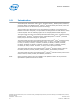
INFORMATION IN THIS DOCUMENT IS PROVIDED IN CONNECTION WITH INTEL PRODUCTS. NO LICENSE, EXPRESS OR IMPLIED, BY ESTOPPEL OR OTHERWISE, TO ANY INTELLECTUAL PROPERTY RIGHTS IS GRANTED BY THIS DOCUMENT.
Contents—Processor Contents Revision History..................................................................................................................9 1.0 Introduction................................................................................................................10 1.1 1.2 1.3 1.4 1.5 1.6 1.7 Supported Technologies.........................................................................................11 Interfaces...................................................................
Processor—Contents 4.3 4.4 4.5 4.6 4.2.3 Requesting Low-Power Idle States...............................................................53 4.2.4 Core C-State Rules....................................................................................54 4.2.5 Package C-States......................................................................................55 4.2.6 Package C-States and Display Resolutions....................................................
Contents—Processor 7.0 Electrical Specifications.............................................................................................. 90 7.1 7.2 7.3 7.4 7.5 7.6 7.7 7.8 Integrated Voltage Regulator..................................................................................90 Power and Ground Lands ...................................................................................... 90 VCC Voltage Identification (VID)..........................................................................
Processor—Figures Figures 1 2 3 4 5 6 7 8 9 10 11 12 13 14 15 16 17 18 19 20 21 22 23 24 25 26 Platform Block Diagram ........................................................................................... 11 Intel® Flex Memory Technology Operations................................................................. 21 PCI Express* Related Register Structures in the Processor............................................ 25 PCI Express* Typical Operation 16 Lanes Mapping....................................
Tables—Processor Tables 1 2 3 4 5 6 7 8 9 10 11 12 13 14 15 16 17 18 19 20 21 22 23 24 25 26 27 28 29 30 31 32 33 34 35 36 37 38 39 40 41 42 43 44 45 46 47 48 49 50 51 52 53 Terminology........................................................................................................... 13 Related Documents..................................................................................................16 Processor DIMM Support by Product...............................................................
Processor—Tables 54 55 56 57 58 59 60 61 GTL Signal Group and Open Drain Signal Group DC Specifications................................ 102 PCI Express* DC Specifications................................................................................103 Platform Environment Control Interface (PECI) DC Electrical Limits...............................103 Processor Loading Specifications.............................................................................. 106 Package Handling Guidelines.............
Revision History—Processor Revision History Revision 001 Description • • 002 003 004 Date Initial Release June 2013 Intel® Core™ September 2013 • • • Added Desktop 4th Generation i7-4771, i5-4440, i5-4440S, i3-4340, i3-4330, i3-4330T, i3-4130, and i3-4130T processors Added Desktop Intel® Pentium® G3430, G3420, G3220, G3420T, G3220T processors Updated Section 4.2.4, Core C-State Rules Updated Section 4.2.
Processor—Introduction 1.0 Introduction The Desktop 4th Generation Intel® Core™ processor family , Desktop Intel® Pentium® processor family, and Desktop Intel® Celeron® processor family are 64-bit, multi-core processors built on 22-nanometer process technology. The processors are designed for a two-chip platform consisting of a processor and Platform Controller Hub (PCH). The processors are designed to be used with the Intel® 8 Series chipset.
Introduction—Processor Figure 1. Platform Block Diagram 1333 / 1600 MT/s 2 DIMMs / CH PCI Express* 3.0 CH A Processor Digital Display Interface (DDI) (3 interfaces) System Memory CH B Note: 2 DIMMs / CH is not supported on all SKUs. Intel® Flexible Display Interface (Intel® FDI) (x2) Direct Media Interface 2.0 (DMI 2.0) (x4) USB 3.0 (up to 6 Ports) Analog Display (VGA) USB 2.0 (8 Ports) Integrated LAN Platform Controller Hub (PCH) SATA, 6 GB/s (up to 6 Ports) SPI Flash PCI Express* 2.
Processor—Introduction • PCLMULQDQ Instruction • Intel® Secure Key • Intel® Transactional Synchronization Extensions - New Instructions (Intel® TSXNI) • PAIR – Power Aware Interrupt Routing • SMEP – Supervisor Mode Execution Protection Note: The availability of the features may vary between processor SKUs. 1.2 Interfaces The processor supports the following interfaces: 1.
Introduction—Processor 1.4 1.5 Thermal Management Support • Digital Thermal Sensor • Adaptive Thermal Monitor • THERMTRIP# and PROCHOT# support • On-Demand Mode • Memory Open and Closed Loop Throttling • Memory Thermal Throttling • External Thermal Sensor (TS-on-DIMM and TS-on-Board) • Render Thermal Throttling • Fan speed control with DTS Package Support The processor socket type is noted as LGA1150. The package is a 37.5 x 37.5 mm Flip Chip Land Grid Array (FCLGA 1150).
Processor—Introduction Term Description ECC Error Correction Code eDP* embedded DisplayPort* EPG Electrical Power Gating EU Execution Unit FMA Floating-point fused Multiply Add instructions FSC Fan Speed Control HDCP High-bandwidth Digital Content Protection HDMI* High Definition Multimedia Interface HFM High Frequency Mode iDCT Inverse Discrete IHS Integrated Heat Spreader GFX Graphics GSA Graphics in System Agent GUI Graphical User Interface IMC Integrated Memory Controller
Introduction—Processor Term Description MLC Mid-Level Cache MSI Message Signaled Interrupt MSL Moisture Sensitive Labeling MSR Model Specific Registers NCTF Non-Critical to Function. NCTF locations are typically redundant ground or non-critical reserved, so the loss of the solder joint continuity at end of life conditions will not affect the overall product functionality.
Processor—Introduction Term Description TAP Test Access Point TCASE The case temperature of the processor, measured at the geometric center of the topside of the TTV IHS. TCC Thermal Control Circuit TCONTROL TCONTROL is a static value that is below the TCC activation temperature and used as a trigger point for fan speed control. When DTS > TCONTROL, the processor must comply to the TTV thermal profile.
Introduction—Processor Document LGA1150 Socket Application Guide Intel® Document Number / Location 328999 8 Series / C220 Series Chipset Family Platform Controller Hub (PCH) Datasheet 328904 Intel® 8 Series / C220 Series Chipset Family Platform Controller Hub (PCH) Specification Update 328905 Intel® 8 Series / C220 Series Chipset Family Platform Controller Hub (PCH) Thermal Mechanical Specifications and Design Guidelines 328906 Advanced Configuration and Power Interface 3.0 http:// www.acpi.
Processor—Interfaces 2.0 Interfaces 2.1 System Memory Interface • Two channels of DDR3/DDR3L Unbuffered Dual In-Line Memory Modules (UDIMM) or DDR3/DDR3L Unbuffered Small Outline Dual In-Line Memory Modules (SODIMM) with a maximum of two DIMMs per channel. • Single-channel and dual-channel memory organization modes • Data burst length of eight for all memory organization modes • Memory data transfer rates of 1333 MT/s and 1600 MT/s • 64-bit wide channels • DDR3/DDR3L I/O Voltage of 1.
Interfaces—Processor 2.1.1 System Memory Technology Supported The Integrated Memory Controller (IMC) supports DDR3/DDR3L protocols with two independent, 64-bit wide channels each accessing one or two DIMMs. The type of memory supported by the processor is dependent on the PCH SKU in the target platform. Note: The IMC supports a maximum of two DDR3/DDR3L DIMMs per channel; thus, allowing up to four device ranks per channel.
Processor—Interfaces Raw Card Version DIMM Capacity DRAM Device Technology DRAM Organization # of DRAM Devices # of Physical Devices Ranks # of Row / Col Address Bits # of Banks Inside DRAM Page Size 2 GB 1 Gb 128 M X 8 16 2 14/10 8 8K 4 GB 2 Gb 256 M X 8 16 2 15/10 8 8K 4 GB 4 Gb 512 M X 8 8 1 15/10 8 8K 8 GB 4 Gb 512 M X 8 16 2 16/10 8 8K B Note: DIMM module support is based on availability and is subject to change. Table 5.
Interfaces—Processor Note: System memory timing support is based on availability and is subject to change. 2.1.3 System Memory Organization Modes The Integrated Memory Controller (IMC) supports two memory organization modes – single-channel and dual-channel. Depending upon how the DIMM Modules are populated in each memory channel, a number of different configurations can exist. Single-Channel Mode In this mode, all memory cycles are directed to a single-channel.
Processor—Interfaces be on opposite channels. Use Dual-Channel Symmetric mode when both Channel A and Channel B DIMM connectors are populated in any order, with the total amount of memory in each channel being the same. When both channels are populated with the same memory capacity and the boundary between the dual channel zone and the single channel zone is the top of memory, the IMC operates completely in Dual-Channel Symmetric mode.
Interfaces—Processor 2.1.3.3 Data Scrambling The system memory controller incorporates a Data Scrambling feature to minimize the impact of excessive di/dt on the platform system memory VRs due to successive 1s and 0s on the data bus.
Processor—Interfaces • PCI Express* extended configuration space. The first 256 bytes of configuration space aliases directly to the PCI Compatibility configuration space. The remaining portion of the fixed 4-KB block of memory-mapped space above that (starting at 100h) is known as extended configuration space. • PCI Express* Enhanced Access Mechanism. Accessing the device configuration space in a flat memory mapped fashion. • Automatic discovery, negotiation, and training of link out of reset.
Interfaces—Processor Figure 3. PCI Express* Related Register Structures in the Processor PCI Express* Device PEG0 PCI-PCI Bridge representing root PCI Express ports (Device 1 and Device 6) PCI Compatible Host Bridge Device (Device 0) DMI PCI Express* extends the configuration space to 4096 bytes per-device/function, as compared to 256 bytes allowed by the conventional PCI specification.
Processor—Interfaces Figure 4. PCI Express* Typical Operation 16 Lanes Mapping 0 1 2 3 4 0 2.3 6 7 8 9 2 10 3 11 4 12 5 13 2 6 14 3 7 15 0 1 1 X 8 Controller 1 X 4 Controller 1 1 X 16 Controller 5 Lane 0 Lane 1 Lane 2 Lane 3 Lane 4 Lane 5 Lane 6 Lane 7 Lane 8 Lane 9 Lane 10 Lane 11 Lane 12 Lane 13 Lane 14 Lane 15 0 1 2 3 4 5 6 7 8 9 10 11 12 13 14 15 Direct Media Interface (DMI) Direct Media Interface (DMI) connects the processor and the PCH. Next generation DMI2 is supported.
Interfaces—Processor • 5 GT/s point-to-point DMI interface to PCH is supported. • Raw bit-rate on the data pins of 5.0 GB/s, resulting in a real bandwidth per pair of 500 MB/s given the 8b/10b encoding used to transmit data across this interface. Does not account for packet overhead and link maintenance. • Maximum theoretical bandwidth on interface of 2 GB/s in each direction simultaneously, for an aggregate of 4 GB/s when DMI x4. • Shares 100-MHz PCI Express* reference clock.
Processor—Interfaces 2.4 Processor Graphics The processor graphics contains a generation 7.5 graphics core architecture. This enables substantial gains in performance and lower power consumption over previous generations. Up to 20 Execution Units are supported depending on the processor SKU.
Interfaces—Processor Figure 5. Processor Graphics Controller Unit Block Diagram 2.5.1 3D and Video Engines for Graphics Processing The Gen 7.5 3D engine provides the following performance and power-management enhancements. 3D Pipeline The 3D graphics pipeline architecture simultaneously operates on different primitives or on different portions of the same primitive. All the cores are fully programmable, increasing the versatility of the 3D Engine. 3D Engine Execution Units • Supports up to 20 EUs.
Processor—Interfaces Vertex Shader (VS) Stage The VS stage performs shading of vertices output by the VF function. The VS unit produces an output vertex reference for every input vertex reference received from the VF unit, in the order received. Geometry Shader (GS) Stage The GS stage receives inputs from the VS stage. Compiled application-provided GS programs, specifying an algorithm to convert the vertices of an input object into some output primitives.
Interfaces—Processor Logical 128-Bit Fixed BLT and 256 Fill Engine This BLT engine accelerates the GUI of Microsoft Windows* operating systems. The 128-bit BLT engine provides hardware acceleration of block transfers of pixel data for many common Windows operations.
Processor—Interfaces The HDMI* interface supports HDMI with 3D, 4K, Deep Color, and x.v.Color. The DisplayPort* interface supports the VESA DisplayPort* Standard Version 1, Revision 2. • The processor supports High-bandwidth Digital Content Protection (HDCP) for high-definition content playback over digital interfaces. • The processor also integrates dedicated a Mini HD audio controller to drive audio on integrated digital display interfaces, such as HDMI* and DisplayPort*.
Interfaces—Processor • Organizing pixels into frames • Optionally scaling the image to the desired size • Re-timing data for the intended target • Formatting data according to the port output standard DisplayPort* DisplayPort* is a digital communication interface that uses differential signaling to achieve a high-bandwidth bus interface designed to support connections between PCs and monitors, projectors, and TV displays.
Processor—Interfaces make up the TMDS data and clock channels. These channels are used to carry video, audio, and auxiliary data. In addition, HDMI carries a VESA DDC. The DDC is used by an HDMI Source to determine the capabilities and characteristics of the Sink. Audio, video, and auxiliary (control/status) data is transmitted across the three TMDS data channels. The video pixel clock is transmitted on the TMDS clock channel and is used by the receiver for data recovery on the three data channels.
Interfaces—Processor embedded DisplayPort* embedded DisplayPort* (eDP*) is an embedded version of the DisplayPort standard oriented towards applications such as notebook and All-In-One PCs. Digital Port D can be configured as eDP. Like DisplayPort, embedded DisplayPort also consists of a Main Link, Auxiliary channel, and an optional Hot-Plug Detect signal. The eDP on the processor can be configured for 2 or 4 lanes. The processor supports embedded DisplayPort* (eDP*) Standard Version 1.
Processor—Interfaces Table 9.
Interfaces—Processor 2.7 2.8 Intel® Flexible Display Interface (Intel® FDI) • The Intel Flexible Display Interface (Intel FDI) passes display data from the processor (source) to the PCH (sink) for display through a display interface on the PCH. • Intel FDI supports 2 lanes at 2.7 GT/s fixed frequency. This can be configured to 1 or 2 lanes depending on the bandwidth requirements. • Intel FDI supports 8 bits per color only. • Side band sync pin (FDI_CSYNC). • Side band interrupt pin (DISP_INT).
Processor—Interfaces Figure 9. PECI Host-Clients Connection Example VTT VTT Q3 nX Q1 nX PECI Q2 1X CPECI <10pF/Node Host / Originator PECI Client Additional PECI Clients Desktop 4th Generation Intel® Core™ Processor Family, Desktop Intel® Pentium® Processor Family, and Desktop Intel® Celeron® Processor Family Datasheet – Volume 1 of 2 December 2013 38 Order No.
Technologies—Processor 3.0 Technologies This chapter provides a high-level description of Intel technologies implemented in the processor. The implementation of the features may vary between the processor SKUs. Details on the different technologies of Intel processors and other relevant external notes are located at the Intel technology web site: http://www.intel.com/technology/ 3.
Processor—Technologies • More reliable: Due to the hardware support, VMMs can now be smaller, less complex, and more efficient. This improves reliability and availability and reduces the potential for software conflicts. • More secure: The use of hardware transitions in the VMM strengthens the isolation of VMs and further prevents corruption of one VM from affecting others on the same system.
Technologies—Processor • Descriptor-Table Exiting — Descriptor-table exiting allows a VMM to protect a guest operating system from an internal (malicious software based) attack by preventing relocation of key system data structures like IDT (interrupt descriptor table), GDT (global descriptor table), LDT (local descriptor table), and TSS (task segment selector).
Processor—Technologies Figure 10.
Technologies—Processor • Memory controller and processor graphics comply with the Intel VT-d 1.
Processor—Technologies Another aspect of the trust decision is the ability of the platform to resist attempts to change the controlling environment. The Intel TXT platform will resist attempts by software processes to change the controlling environment or bypass the bounds set by the controlling environment.
Technologies—Processor Intel recommends enabling Intel HT Technology with Microsoft Windows* 8 and Microsoft Windows* 7 and disabling Intel HT Technology using the BIOS for all previous versions of Windows* operating systems. For more information on Intel HT Technology, see http://www.intel.com/technology/platform-technology/hyperthreading/. 3.4 Intel® Turbo Boost Technology 2.0 The Intel Turbo Boost Technology 2.
Processor—Technologies digital signal processing software. FMA improves performance in face detection, professional imaging, and high performance computing. Gather operations increase vectorization opportunities for many applications. In addition to the vector extensions, this generation of Intel processors adds new bit manipulation instructions useful in compression, encryption, and general purpose software. For more information on Intel AVX, see http://www.intel.com/software/avx 3.
Technologies—Processor extensions to achieve the performance of fine-grain locking while actually programming using coarse-grain locks. Details on Intel TSX-NI are in the Intel® Architecture Instruction Set Extensions Programming Reference. 3.8 Intel® 64 Architecture x2APIC The x2APIC architecture extends the xAPIC architecture that provides key mechanisms for interrupt delivery. This extension is primarily intended to increase processor addressability.
Processor—Technologies Note: • The semantics for accessing APIC registers have been revised to simplify the programming of frequently-used APIC registers by system software. Specifically, the software semantics for using the Interrupt Command Register (ICR) and End Of Interrupt (EOI) registers have been modified to allow for more efficient delivery and dispatching of interrupts. • The x2APIC extensions are made available to system software by enabling the local x2APIC unit in the “x2APIC” mode.
Power Management—Processor 4.0 Power Management This chapter provides information on the following power management topics: Figure 11.
Processor—Power Management 4.1 Advanced Configuration and Power Interface (ACPI) States Supported This section describes the ACPI states supported by the processor. Table 11. System States State G0/S0 G1/S3-Cold Full On Mode. Suspend-to-RAM (STR). Context saved to memory (S3-Hot state is not supported by the processor). G1/S4 Suspend-to-Disk (STD). All power lost (except wakeup on PCH). G2/S5 Soft off. All power lost (except wakeup on PCH). Total reboot. G3 Table 12. Description Mechanical off.
Power Management—Processor Table 15. Direct Media Interface (DMI) States State Table 16. L0 Full on – Active transfer state. L0s First Active Power Management low-power state – Low exit latency. L1 Lowest Active Power Management – Longer exit latency. L3 Lowest power state (power-off) – Longest exit latency. G, S, and C Interface State Combinations Global (G) State Table 17. 4.
Processor—Power Management 4.2.2 • Multiple frequency and voltage points for optimal performance and power efficiency. These operating points are known as P-states. • Frequency selection is software controlled by writing to processor MSRs. The voltage is optimized based on the selected frequency and the number of active processor cores. — Once the voltage is established, the PLL locks on to the target frequency. — All active processor cores share the same frequency and voltage.
Power Management—Processor Figure 13. Thread and Core C-State Entry and Exit C0 MWAIT(C1), HLT MWAIT(C1), HLT (C1E Enabled) C1 C1E MWAIT(C7), P_LVL4 I/O Read MWAIT(C3), P_LVL2 I/O Read MWAIT(C6), P_LVL3 I/O Read C3 C6 C7 While individual threads can request low-power C-states, power saving actions only take place once the core C-state is resolved. Core C-states are automatically resolved by the processor.
Processor—Power Management Note: When P_LVLx I/O instructions are used, MWAIT sub-states cannot be defined. The MWAIT sub-state is always zero if I/O MWAIT redirection is used. By default, P_LVLx I/O redirections enable the MWAIT 'break on EFLAGS.IF’ feature that triggers a wakeup on an interrupt, even if interrupts are masked by EFLAGS.IF. 4.2.
Power Management—Processor Core C6 State Individual threads of a core can enter the C6 state by initiating a P_LVL3 I/O read or an MWAIT(C6) instruction. Before entering core C6 state, the core will save its architectural state to a dedicated SRAM. Once complete, a core will have its voltage reduced to zero volts. During exit, the core is powered on and its architectural state is restored.
Processor—Power Management — For package C-states, the processor is not required to enter C0 state before entering any other C-state. — Entry into a package C-state may be subject to auto-demotion – that is, the processor may keep the package in a deeper package C-state than requested by the operating system if the processor determines, using heuristics, that the deeper C-state results in better power/performance. The processor exits a package C-state when a break event is detected.
Power Management—Processor Figure 14. Package C-State Entry and Exit C0 C3 C6 C1 C7 Package C0 State This is the normal operating state for the processor. The processor remains in the normal state when at least one of its cores is in the C0 or C1 state or when the platform has not granted permission to the processor to go into a low-power state. Individual cores may be in lower power idle states while the package is in C0 state.
Processor—Power Management Package C2 State Package C2 state is an internal processor state that cannot be explicitly requested by software. A processor enters Package C2 state when: • All cores and graphics have requested a C3 or deeper power state; however, constraints (LTR, programmed timer events in the near future, and so on) prevent entry to any state deeper than C 2 state. Or, • All cores and graphics are in the C3 or deeper power states, and a memory access request is received.
Power Management—Processor Note: Package C6 state is the deepest C-state supported on discrete graphics systems with PCI Express Graphics (PEG). Package C7 state is the deepest C-state supported on integrated graphics systems (or switchable graphics systems during integrated graphics mode). However, in most configurations, package C6 will be more energy efficient than package C7 state.
Processor—Power Management Number of Displays 1 Native Resolution Deepest Available Package CState Single 2880x1620 60 Hz PC3 Single 2880x1800 60 Hz PC3 Single 3200x1800 60 Hz PC3 Single 3200x2000 60 Hz PC3 Single 3840x2160 60 Hz PC3 Single 3840x2160 30 Hz PC3 Single 4096x2160 24 Hz PC3 Multiple 800x600 60 Hz PC6 Multiple 1024x768 60 Hz PC6 Multiple 1280x1024 60 Hz PC6 Multiple 1920x1080 60 Hz PC3 Multiple 1920x1200 60 Hz PC3 Multiple 1920x1440 60 Hz PC3 Multiple
Power Management—Processor • Reduced possible overshoot/undershoot signal quality issues seen by the processor I/O buffer receivers caused by reflections from potentially unterminated transmission lines. When a given rank is not populated, the corresponding chip select and CKE signals are not driven. At reset, all rows must be assumed to be populated, until it can be determined that the rows are not populated.
Processor—Power Management Selection of power modes should be according to power-performance or thermal trade-offs of a given system: • When trying to achieve maximum performance and power or thermal consideration is not an issue – use no power-down • In a system which tries to minimize power-consumption, try using the deepest power-down mode possible – PPD/DLL-off with a low idle timer value • In high-performance systems with dense packaging (that is, tricky thermal design) the power-down mode should
Power Management—Processor assertion with all pages closed). Pre-charge power-down provides greater power savings, but has a bigger performance impact since all pages will first be closed before putting the devices in power-down mode. If dynamic power-down is enabled, all ranks are powered up before doing a refresh cycle and all ranks are powered down at the end of refresh. 4.3.2.4 DRAM I/O Power Management Unused signals should be disabled to save power and reduce electromagnetic interference.
Processor—Power Management 4.6 Graphics Power Management 4.6.1 Intel® Rapid Memory Power Management (Intel® RMPM) Intel Rapid Memory Power Management (Intel RMPM) conditionally places memory into self-refresh when the processor is in package C3 or deeper power state to allow the system to remain in the lower power states longer for memory not reserved for graphics memory.
Thermal Management—Processor 5.0 Thermal Management This chapter provides both component-level and system-level thermal management. Topics covered include processor thermal specifications, thermal profiles, thermal metrology, fan speed control, adaptive thermal monitor, THERMTRIP# signal, Digital Thermal Sensor (DTS), Intel Turbo Boost Technology, package power control, power plane control, and turbo time parameter.
Processor—Thermal Management Table 21. Product Desktop Processor Thermal Specifications PCG8 Max Power Packag e C1E (W) 1, 2, 5, 9 Quad Core Processor with Graphics Quad Core Processor with Graphics Quad Core Processor with Graphics Quad Core Processor with Graphics Dual Core Processor with Graphics 2013D 2013C 2013B 26 23 Max Power Packag e C3 (W) 1, 3, Min Power Package C3 (W)9 5, 9 20 17 Max Power Packag e C6 (W) 1, 4, Max Power Package C7 (W) 1, 4, 5, 9 5, 9 1.0 1.0 3.5 3.
Thermal Management—Processor 5.1.1 Processor (PCG 2013D) Thermal Profile Figure 15. Thermal Test Vehicle Thermal Profile for Processor (PCG 2013D) TTV Case Temperature (°C) 80 75 TCASE = 0.33 * Power + 45.0 70 65 60 55 50 45 40 0 20 40 60 80 100 TTV Power (W) See the following table for discrete points that constitute the thermal profile. Table 22.
Processor—Thermal Management 5.1.2 Processor (PCG 2013C) Thermal Profile Figure 16. Thermal Test Vehicle Thermal Profile for Processor (PCG 2013C) See the following table for discrete points that constitute the thermal profile. Table 23. Thermal Test Vehicle Thermal Profile for Processor (PCG 2013C) Power (W) TCASE_MAX (°C) Power (W) TCASE_MAX (°C) Y = 0.41 * Power + 44.7 30 57.00 0 44.7 32 57.82 2 45.52 34 58.64 4 46.34 36 59.46 6 47.16 38 60.28 8 47.98 40 61.10 10 48.
Thermal Management—Processor Power (W) TCASE_MAX (°C) 62 70.12 64 70.94 65 71.35 5.1.3 Processor (PCG 2013B) Thermal Profile Figure 17. Thermal Test Vehicle Thermal Profile for Processor (PCG 2013B) See the following table for discrete points that constitute the thermal profile. Table 24. Thermal Test Vehicle Thermal Profile for Processor (PCG 2013B) Power (W) TCASE_MAX (°C) Power (W) TCASE_MAX (°C) Power (W) TCASE_MAX (°C) Y = 0.51 * Power + 48.5 20 58.70 42 69.92 0 48.50 22 59.
Processor—Thermal Management 5.1.4 Processor (PCG 2013A) Thermal Profile Figure 18. Thermal Test Vehicle Thermal Profile for Processor (PCG 2013A) See the following table for discrete points that constitute the thermal profile. Table 25. Thermal Test Vehicle Thermal Profile for Processor (PCG 2013A) Power (W) TCASE_MAX (°C) Power (W) TCASE_MAX (°C) Y = 0.51 * Power + 48.5 30 63.80 0 48.50 32 64.82 2 49.52 34 65.84 4 50.54 35 66.35 6 51.56 8 52.58 10 53.60 12 54.62 14 55.
Thermal Management—Processor 5.2 Thermal Metrology The maximum Thermal Test Vehicle (TTV) case temperatures (TCASE-MAX) can be derived from the data in the appropriate TTV thermal profile earlier in this chapter. The TTV TCASE is measured at the geometric top center of the TTV integrated heat spreader (IHS). The following figure illustrates the location where TCASE temperature measurements should be made. Figure 19. Thermal Test Vehicle (TTV) Case Temperature (TCASE) Measurement Location 37.
Processor—Thermal Management The ΨCA point at DTS = -1 defines the minimum ΨCA required at TDP considering the worst case system design TAMBIENT design point: ΨCA = (TCASE-MAX – TAMBIENT-TARGET) / TDP For example, for a 95 W TDP part, the Tcase maximum is 72.6 °C and at a worst case design point of 40 °C local ambient this will result in: ΨCA = (72.6 – 40) / 95 = 0.34 °C/W Similarly for a system with a design target of 45 °C ambient, the ΨCA at DTS = -1 needed will be 0.29 °C/W.
Thermal Management—Processor Table 26. Digital Thermal Sensor (DTS) 1.1 Thermal Solution Performance Above TCONTROL Processor TDP ΨCA at DTS = TCONTROL1, 2 At System TAMBIENTMAX = 30 °C ΨCA at DTS = -1 At System TAMBIENT-MAX = 40 °C ΨCA at DTS = -1 At System TAMBIENT-MAX = 45 °C ΨCA at DTS = -1 At System TAMBIENTMAX = 50 °C 84 W 0.627 0.390 0.330 0.270 65 W 0.793 0.482 0.405 0.328 45 W 1.207 0.699 0.588 0.477 35 W 1.406 0.753 0.610 0.467 Notes: 1.
Processor—Thermal Management Figure 21. Digital Thermal Sensor (DTS) Thermal Profile Definition Table 27. Thermal Margin Slope PCG 2013D 2013C 2013B 2013A 5.5 Die Configuration (Native) Core + GT TDP (W) TCC Activation Temperature (°C) MSR 1A2h 23:16 Temperature Control Offset MSR 1A2h 15:8 Thermal Margin Slope (°C / W) 4+2 (4+2) 84 100 20 0.654 4+0 (4+2) 82 100 20 0.671 4+2 (4+2) 65 92 6 0.722 2+2 (2+2) 54 100 20 1.031 2+1 (2+2) 53 100 20 1.
Thermal Management—Processor 5.6 Adaptive Thermal Monitor The Adaptive Thermal Monitor feature provides an enhanced method for controlling the processor temperature when the processor silicon exceeds the Thermal Control Circuit (TCC) activation temperature. Adaptive Thermal Monitor uses TCC activation to reduce processor power using a combination of methods.
Processor—Thermal Management after 1 ms the processor is still too hot (the temperature has not dropped below the TCC activation point, DTS still = 0 and PROCHOT is still active), then a second frequency and voltage transition will take place. This sequence of temperature checking and frequency and voltage reduction will continue until either the minimum frequency has been reached or the processor temperature has dropped below the TCC activation point.
Thermal Management—Processor If TM1 and TM2 have both been active for greater than 20 ms and the processor temperature has not dropped below the TCC activation point, the Critical Temperature Flag in the IA32_THERM_STATUS MSR will be set. This flag is an indicator of a catastrophic thermal solution failure and that the processor cannot reduce its temperature.
Processor—Thermal Management a backup in case of system cooling failure. The system thermal design should allow the power delivery circuitry to operate within its temperature specification even while the processor is operating at its Thermal Design Power. 5.
Thermal Management—Processor have the capability of generating interrupts using the core's local APIC. Refer to the Intel® 64 and IA-32 Architectures Software Developer’s Manual for specific register and programming details. 5.8.1 Digital Thermal Sensor Accuracy (Taccuracy) The error associated with DTS measurements will not exceed ±5 °C within the entire operating range. 5.
Processor—Thermal Management • Uncharacterized workloads may exist that could result in higher turbo frequencies and power. If that were to happen, the processor Thermal Control Circuitry (TCC) would protect the processor. The TCC protection must be enabled by the platform for the product to be within specification. An illustration of Intel Turbo Boost Technology power control is shown in the following sections and figures.
Thermal Management—Processor Figure 22. Package Power Control 5.9.3 Turbo Time Parameter Turbo Time Parameter is a mathematical parameter (units in seconds) that controls the Intel Turbo Boost Technology algorithm using an average of energy usage. During a maximum power turbo event of about 1.25 x TDP, the processor could sustain Power_Limit_2 for up to approximately 1.5 the Turbo Time Parameter.
Processor—Signal Description 6.0 Signal Description This chapter describes the processor signals. The signals are arranged in functional groups according to the associated interface or category. The following notations are used to describe the signal type. Signal Type Notation I Input pin O Output pin I/O Bi-directional Input/Output pin The signal description also includes the type of buffer used for the particular signal (see the following table). Table 29.
Signal Description—Processor Signal Name Direction / Buffer Type SA_RAS# RAS Control Signal: This signal is used with SA_CAS# and SA_WE# (along with SA_CS#) to define the SRAM Commands. O DDR3/DDR3L SA_CAS# CAS Control Signal: This signal is used with SA_RAS# and SA_WE# (along with SA_CS#) to define the SRAM Commands. O DDR3/DDR3L SA_DQS[8:0] SA_DQSN[8:0] Data Strobes: SA_DQS[8:0] and its complement signal group make up a differential strobe pair.
Processor—Signal Description Signal Name Description Direction / Buffer Type SB_CK[3:0] SDRAM Differential Clock: Channel B SDRAM Differential clock signal pair. The crossing of the positive edge of SB_CK and the negative edge of its complement SB_CK# are used to sample the command and control signals on the SDRAM. O DDR3/DDR3L SB_CKE[3:0] Clock Enable: (1 per rank). These signals are used to: • Initialize the SDRAMs during power-up. • Power-down SDRAM ranks.
Signal Description—Processor 6.3 Reset and Miscellaneous Signals Table 33. Reset and Miscellaneous Signals Signal Name Description CFG[19:0] Configuration Signals: The CFG signals have a default value of '1' if not terminated on the board. • CFG[1:0]: Reserved configuration lane. A test point may be placed on the board for these lanes. • CFG[2]: PCI Express* Static x16 Lane Numbering Reversal. — 1 = Normal operation — 0 = Lane numbers reversed.
Processor—Signal Description 6.4 PCI Express*-Based Interface Signals Table 34. PCI Express* Graphics Interface Signals Signal Name Description Direction / Buffer Type PCI Express Resistance Compensation PEG_RCOMP I A PEG_RXP[15:0] PEG_RXN[15:0] PCI Express Receive Differential Pair I PCI Express PEG_TXP[15:0] PEG_TXN[15:0] PCI Express Transmit Differential Pair O PCI Express 6.5 Display Interface Signals Table 35.
Signal Description—Processor 6.7 Phase Locked Loop (PLL) Signals Table 37. Phase Locked Loop (PLL) Signals Signal Name Description Direction / Buffer Type BCLKP BCLKN Differential bus clock input to the processor I Diff Clk DPLL_REF_CLKP DPLL_REF_CLKN Embedded Display Port PLL Differential Clock In: 135 MHz I Diff Clk SSC_DPLL_REF_CLKP SSC_ DPLL_REF_CLKN Spread Spectrum Embedded DisplayPort PLL Differential Clock In: 135 MHz I Diff Clk 6.8 Testability Signals Table 38.
Processor—Signal Description 6.9 Error and Thermal Protection Signals Table 39. Error and Thermal Protection Signals Signal Name Description Direction / Buffer Type CATERR# Catastrophic Error: This signal indicates that the system has experienced a catastrophic error and cannot continue to operate. The processor will set this for non-recoverable machine check errors or other unrecoverable internal errors.
Signal Description—Processor 6.11 Processor Power Signals Table 41. Processor Power Signals Signal Name Description Direction / Buffer Type VCC Processor core power rail. Ref VCCIO_OUT Processor power reference for I/O. Ref VDDQ Processor I/O supply voltage for DDR3. Ref VCOMP_OUT Processor power reference for PEG/Display RCOMP.
Processor—Electrical Specifications 7.0 Electrical Specifications This chapter provides the processor electrical specifications including integrated voltage regulator (VR), VCC Voltage Identification (VID), reserved and unused signals, signal groups, Test Access Points (TAP), and DC specifications. 7.1 Integrated Voltage Regulator A new feature to the processor is the integration of platform voltage regulators into the processor.
Electrical Specifications—Processor Table 45. Voltage Regulator (VR) 12.5 Voltage Identification B i t 7 B i t 6 B i t 5 B i t 4 B i t 3 B i t 2 B i t 1 B i t 0 Hex 0 0 0 0 0 0 0 0 00h 0 0 0 0 0 0 0 1 0 0 0 0 0 0 1 0 VCC B i t 7 B i t 6 B i t 5 B i t 4 B i t 3 B i t 2 B i t 1 B i t 0 Hex VCC 0.0000 0 0 1 0 0 0 0 1 21h 0.8200 01h 0.5000 0 0 1 0 0 0 1 0 22h 0.8300 02h 0.5100 0 0 1 0 0 0 1 1 23h 0.
Processor—Electrical Specifications B i t 7 B i t 6 B i t 5 B i t 4 B i t 3 B i t 2 B i t 1 B i t 0 Hex 0 1 0 0 0 0 1 0 42h 0 1 0 0 0 0 1 1 0 1 0 0 0 1 0 0 1 0 0 0 1 0 1 0 0 0 0 1 0 0 0 1 0 0 1 0 VCC B i t 7 B i t 6 B i t 5 B i t 4 B i t 3 B i t 2 B i t 1 B i t 0 Hex VCC 1.1500 0 1 1 0 0 1 0 0 64h 1.4900 43h 1.1600 0 1 1 0 0 1 0 1 65h 1.5000 0 44h 1.1700 0 1 1 0 0 1 1 0 66h 1.5100 0 1 45h 1.
Electrical Specifications—Processor B i t 7 B i t 6 B i t 5 B i t 4 B i t 3 B i t 2 B i t 1 B i t 0 Hex 1 0 0 0 0 1 1 0 86h 1 0 0 0 0 1 1 1 1 0 0 0 1 0 0 1 0 0 0 1 0 1 0 0 0 1 1 0 0 0 1 0 0 1 0 1 VCC B i t 7 B i t 6 B i t 5 B i t 4 B i t 3 B i t 2 B i t 1 B i t 0 Hex VCC 1.8300 1 0 1 0 1 0 0 0 A8h 2.1700 87h 1.8400 1 0 1 0 1 0 0 1 A9h 2.1800 0 88h 1.8500 1 0 1 0 1 0 1 0 AAh 2.1900 0 1 89h 1.
Processor—Electrical Specifications B i t 7 B i t 6 B i t 5 B i t 4 B i t 3 B i t 2 B i t 1 B i t 0 Hex 1 1 0 0 1 0 1 0 CAh 1 1 0 0 1 0 1 1 1 1 0 0 1 1 0 1 1 0 0 1 1 1 1 0 0 1 1 1 0 0 1 1 0 1 1 1 VCC B i t 7 B i t 6 B i t 5 B i t 4 B i t 3 B i t 2 B i t 1 B i t 0 Hex VCC 2.5100 1 1 1 0 1 1 0 0 ECh 2.8500 CBh 2.5200 1 1 1 0 1 1 0 1 EDh 2.8600 0 CCh 2.5300 1 1 1 0 1 1 1 0 EEh 2.8700 0 1 CDh 2.
Electrical Specifications—Processor 7.
Processor—Electrical Specifications Signal Group Type DDR3 / DDR3L Data Signals Signals 2 Single ended DDR3/DDR3L Bidirectional SA_DQ[63:0], SB_DQ[63:0] Differential DDR3/DDR3L Bidirectional SA_DQSP[7:0], SA_DQSN[7:0], SB_DQSP[7:0], SB_DQSN[7:0] DDR3 / DDR3L Compensation Analog Input SM_RCOMP[2:0] DDR3 / DDR3L Reference Voltage Signals DDR3/DDR3L Output SM_VREF, SA_DIMM_VREFDQ, SB_DIMM_VREFDQ Testability (ITP/XDP) Single ended CMOS Input TCK, TDI, TMS, TRST# Single ended GTL TDO Single
Electrical Specifications—Processor Signal Group Type Signals Test Point RSVD_TP Other SKTOCC#, PCI Express* Graphics Differential PCI Express Input PEG_RXP[15:0], PEG_RXN[15:0] Differential PCI Express Output PEG_TXP[15:0], PEG_TXN[15:0] Single ended Analog Input PEG_RCOMP Digital Media Interface (DMI) Differential DMI Input DMI_RXP[3:0], DMI_RXN[3:0] Differential DMI Output DMI_TXP[3:0], DMI_TXN[3:0] Digital Display Interface Differential DDI Output DDIB_TXP[3:0], DDIB_TXN[3:0], D
Processor—Electrical Specifications • AC tolerances for all DC rails include dynamic load currents at switching frequencies up to 1 MHz. 7.8 Voltage and Current Specifications Table 47. Processor Core Active and Idle Mode DC Voltage and Current Specifications Symbol Parameter Min Typ 2013D: 2013C: 2013B: 2013A: 1.75 1.75 1.75 1.75 Max Unit Note1 1.86 V 2 1.65 V 2 Operational VID VID Range 1.65 Idle VID (package C6/C7) VID Range 1.
Electrical Specifications—Processor Symbol Parameter Min Typ Max Unit Note1 — — 48 A 4, 8 ICC 2013A PCG ICC PMAX 2013D PCG PMAX — — 153 W 9 PMAX 2013C PCG PMAX — — 121 W 9 PMAX 2013B PCG PMAX — — 99 W 9 PMAX 2013A PCG PMAX — — 83 W 9 Notes: 1. Unless otherwise noted, all specifications in this table are based on estimates and simulations or empirical data. 2.
Processor—Electrical Specifications Table 49. VCCIO_OUT, VCOMP_OUT, and VCCIO_TERM Symbol Parameter Typ Max Units 1.0 — V — 300 mA Notes VCCIO_OUT Termination Voltage ICCIO_OUT Maximum External Load VCOMP_OUT Termination Voltage 1.0 — V 1 VCCIO_TERM Termination Voltage 1.0 — V 2 Notes: 1. VCOMP_OUT may only be used to connect to PEG_RCOMP and DP_RCOMP. 2. Internal processor power for signal termination. Table 50.
Electrical Specifications—Processor Symbol Parameter Min Typ Max Units Notes1 RON_DN(CTL) DDR3/DDR3L Control Buffer pull-down Resistance 19 25 31 Ω 5, 11, 13 RON_UP(RST) DDR3/DDR3L Reset Buffer pull-up Resistance 40 80 130 Ω — RON_DN(RST) DDR3/DDR3L Reset Buffer pull-up Resistance 40 80 130 Ω — ILI Input Leakage Current (DQ, CK) 0V 0.2*VDDQ 0.8*VDDQ — — 0.7 mA — ILI Input Leakage Current (CMD, CTL) 0V 0.2*VDDQ 0.8*VDDQ — — 1.
Processor—Electrical Specifications Table 52. embedded DisplayPort* (eDP*) Group DC Specifications Symbol Parameter Min Typ Max Units VIL HPD Input Low Voltage 0.02 — 0.21 V VIH HPD Input High Voltage 0.84 — 1.05 V VOL eDP_DISP_UTIL Output Low Voltage 0.1*VCC — — V VOH eDP_DISP_UTIL Output High Voltage 0.
Electrical Specifications—Processor Symbol Parameter Max Units Notes1 VIH Input High Voltage (other GTL) VCCIO_TERM * 0.72 — V 2, 4 RON Buffer on Resistance (CFG/BPM) 16 24 Ω — RON Buffer on Resistance (other GTL) 12 28 Ω — Input Leakage Current — ±150 μA 3 ILI Notes: 1. 2. 3. 4. Table 55. Min Unless otherwise noted, all specifications in this table apply to all processor frequencies. The VCCIO_OUT referred to in these specifications refers to instantaneous VCCIO_OUT.
Processor—Electrical Specifications Symbol Definition and Conditions Min Max Units Notes1 Vn Negative-Edge Threshold Voltage 0.275 * VCCIO_TERM 0.500 * VCCIO_TERM V — Vp Positive-Edge Threshold Voltage 0.550 * VCCIO_TERM 0.725 * VCCIO_TERM V — Cbus Bus Capacitance per Node N/A 10 pF — Cpad Pad Capacitance 0.7 1.8 pF — Ileak000 leakage current at 0 V — 0.6 mA — Ileak025 leakage current at 0.25* VCCIO_TERM — 0.4 mA — Ileak050 leakage current at 0.
Package Mechanical Specifications—Processor 8.0 Package Mechanical Specifications The processor is packaged in a Flip-Chip Land Grid Array package that interfaces with the motherboard using the LGA1150 socket. The package consists of a processor mounted on a substrate land-carrier. An integrated heat spreader (IHS) is attached to the package substrate and core and serves as the mating surface for processor thermal solutions, such as a heatsink.
Processor—Package Mechanical Specifications mechanical system or component testing should not exceed the maximum limits. The processor package substrate should not be used as a mechanical reference or loadbearing surface for thermal and mechanical solution. Table 57. Processor Loading Specifications Parameter Minimum Maximum Notes Static Compressive Load — 600 N [135 lbf] 1, 2, 3 Dynamic Compressive Load — 712 N [160 lbf] 1, 3, 4 Notes: 1.
Package Mechanical Specifications—Processor Table 59. Processor Materials Component 8.7 Material Integrated Heat Spreader (IHS) Nickel Plated Copper Substrate Fiber Reinforced Resin Substrate Lands Gold Plated Copper Processor Markings The following figure shows the top-side markings on the processor. This diagram aids in the identification of the processor. Figure 25. Processor Top-Side Markings 8.
Processor—Package Mechanical Specifications Figure 26. Processor Package Land Coordinates 8.9 Processor Storage Specifications The following table includes a list of the specifications for device storage in terms of maximum and minimum temperatures and relative humidity. These conditions should not be exceeded in storage or transportation. Table 60. Processor Storage Specifications Parameter Description Minimum Maximum Notes Tabsolute storage The non-operating device storage temperature.
Package Mechanical Specifications—Processor Parameter Description RHsustained storage The maximum device storage relative humidity for a sustained period of time. TIMEsustained storage A prolonged or extended period of time; typically associated with customer shelf life. Minimum Maximum 60% @ 24 °C 0 Months 6 Months Notes 5, 6 6 Notes: 1. Refers to a component device that is not assembled in a board or socket that is not to be electrically connected to a voltage reference or I/O signals. 2.
Processor—Processor Ball and Signal Information 9.0 Processor Ball and Signal Information This chapter provides processor ball information. The following table provides the ball list by signal name. Note: References to SA_ECC_CB[7:0] and SB_ECC_CB[7:0] are for processor SKUs that support ECC. These signals are reserved on the Desktop 4th Generation Intel® Core™ processor family. Table 61.
Processor Ball and Signal Information—Processor Signal Name Ball # DPLL_REF_CLKN W6 PEG_RXP14 K5 PEG_TXP4 C8 DPLL_REF_CLKP W5 PEG_RXP15 L4 PEG_TXP5 B7 EDP_DISP_UTIL E16 PEG_RXP2 E13 PEG_TXP6 A6 FC_K9 K9 PEG_RXP3 D12 PEG_TXP7 B5 FC_Y7 Y7 PEG_RXP4 E11 PEG_TXP8 E1 FDI_CSYNC D16 PEG_RXP5 F10 PEG_TXP9 F2 FDI0_TX0N0 B14 PEG_RXP6 E9 PM_SYNC P36 FDI0_TX0N1 C13 PEG_RXP7 F8 PRDY# L39 FDI0_TX0P0 A14 PEG_RXP8 D3 PREQ# L37 FDI0_TX0P1 B13 PEG_RXP9 E4 PROCHOT#
Processor—Processor Ball and Signal Information Signal Name Ball # Signal Name RSVD J17 RSVD_TP RSVD J40 RSVD Ball # Signal Name Ball # P37 SA_DQ20 AM37 SA_BS0 AV12 SA_DQ21 AM38 J9 SA_BS1 AY11 SA_DQ22 AP37 RSVD L10 SA_BS2 AT21 SA_DQ23 AP40 RSVD L12 SA_CAS# AU9 SA_DQ24 AV37 RSVD M10 SA_CK0 AY15 SA_DQ25 AW37 RSVD M11 SA_CK1 AW15 SA_DQ26 AU35 RSVD M38 SA_CK2 AV14 SA_DQ27 AV35 RSVD N35 SA_CK3 AW13 SA_DQ28 AT37 RSVD P33 SA_CKE0 AV22 SA_DQ29 AU37
Processor Ball and Signal Information—Processor Signal Name Ball # Signal Name Ball # Signal Name Ball # SA_DQ53 AL3 SA_ECC_CB3 AV31 SB_CKE1 AY29 SA_DQ54 AJ2 SA_ECC_CB4 AT33 SB_CKE2 AU28 SA_DQ55 AJ1 SA_ECC_CB5 AU33 SB_CKE3 AU29 SA_DQ56 AG1 SA_ECC_CB6 AT31 SB_CKN0 AM21 SA_DQ57 AG4 SA_ECC_CB7 AW31 SB_CKN1 AP21 SA_DQ58 AE3 SA_MA0 AU13 SB_CKN2 AN21 SA_DQ59 AE4 SA_MA1 AV16 SB_CKN3 AP20 SA_DQ6 AF37 SA_MA10 AW11 SB_CS#0 AP17 SA_DQ60 AG2 SA_MA11 AV19 SB_CS#
Processor—Processor Ball and Signal Information Signal Name Ball # Signal Name Ball # Signal Name Ball # SB_DQ3 AH35 SB_DQ62 AF6 SB_MA13 AR15 SB_DQ30 AP29 SB_DQ63 AF7 SB_MA14 AV27 SB_DQ31 AP28 SB_DQ7 AH34 SB_MA15 AY28 SB_DQ32 AR12 SB_DQ8 AL34 SB_MA2 AM22 SB_DQ33 AP12 SB_DQ9 AL35 SB_MA3 AM23 SB_DQ34 AL13 SB_DQS0 AF35 SB_MA4 AP23 SB_DQ35 AL12 SB_DQS1 AL33 SB_MA5 AL23 SB_DQ36 AR13 SB_DQS2 AP33 SB_MA6 AY24 SB_DQ37 AP13 SB_DQS3 AN28 SB_MA7 AV25 SB_DQ38
Processor Ball and Signal Information—Processor Signal Name Ball # Signal Name Ball # Signal Name Ball # VCC A24 VCC E29 VCC J22 VCC A25 VCC E30 VCC J23 VCC A26 VCC E31 VCC J24 VCC A27 VCC E32 VCC J25 VCC A28 VCC E33 VCC J26 VCC A29 VCC E34 VCC J27 VCC A30 VCC E35 VCC J28 VCC B25 VCC F23 VCC J29 VCC B27 VCC F25 VCC J30 VCC B29 VCC F27 VCC J31 VCC B31 VCC F29 VCC J32 VCC B33 VCC F31 VCC J33 VCC B35 VCC F33 VCC J34 VCC C24
Processor—Processor Ball and Signal Information Signal Name Ball # Signal Name Ball # Signal Name Ball # VCC L28 VDDQ AU20 VSS AC34 VCC L29 VDDQ AU24 VSS AC35 VCC L30 VDDQ AV10 VSS AC36 VCC L31 VDDQ AV11 VSS AC37 VCC L32 VDDQ AV13 VSS AC38 VCC L33 VDDQ AV18 VSS AC39 VCC L34 VDDQ AV23 VSS AC40 VCC M13 VDDQ AV8 VSS AC6 VCC M15 VDDQ AW16 VSS AC7 VCC M17 VDDQ AY12 VSS AD1 VCC M19 VDDQ AY14 VSS AD2 VCC M21 VDDQ AY9 VSS AD3 VCC M23 V
Processor Ball and Signal Information—Processor Signal Name Ball # Signal Name Ball # Signal Name Ball # VSS AG40 VSS AK14 VSS AM2 VSS AG5 VSS AK18 VSS AM24 VSS AG8 VSS AK19 VSS AM27 VSS AH1 VSS AK24 VSS AM3 VSS AH2 VSS AK25 VSS AM30 VSS AH3 VSS AK26 VSS AM31 VSS AH33 VSS AK27 VSS AM32 VSS AH36 VSS AK28 VSS AM33 VSS AH4 VSS AK29 VSS AM34 VSS AH5 VSS AK30 VSS AM35 VSS AH8 VSS AK36 VSS AM36 VSS AJ11 VSS AK4 VSS AM4 VSS AJ14 VSS
Processor—Processor Ball and Signal Information Signal Name Ball # Signal Name Ball # Signal Name Ball # VSS AP24 VSS AT15 VSS AV7 VSS AP27 VSS AT16 VSS AW26 VSS AP30 VSS AT2 VSS AW3 VSS AP36 VSS AT24 VSS AW30 VSS AP4 VSS AT25 VSS AW32 VSS AP5 VSS AT26 VSS AW34 VSS AR11 VSS AT27 VSS AW36 VSS AR14 VSS AT28 VSS AW7 VSS AR16 VSS AT29 VSS AY17 VSS AR17 VSS AT3 VSS AY23 VSS AR18 VSS AT30 VSS AY26 VSS AR19 VSS AT32 VSS AY27 VSS AR20
Processor Ball and Signal Information—Processor Signal Name Ball # Signal Name Ball # Signal Name Ball # VSS C6 VSS F22 VSS H30 VSS D11 VSS F24 VSS H32 VSS D13 VSS F26 VSS H34 VSS D15 VSS F28 VSS H36 VSS D17 VSS F30 VSS H39 VSS D2 VSS F32 VSS H4 VSS D23 VSS F34 VSS H7 VSS D24 VSS F36 VSS H8 VSS D26 VSS F4 VSS H9 VSS D28 VSS F7 VSS J11 VSS D30 VSS G11 VSS J14 VSS D32 VSS G12 VSS J18 VSS D34 VSS G13 VSS J19 VSS D36 VSS G14
Processor—Processor Ball and Signal Information Signal Name Ball # Signal Name Ball # Signal Name Ball # VSS K40 VSS N3 VSS T7 VSS K7 VSS N33 VSS U2 VSS L11 VSS N34 VSS U33 VSS L13 VSS N39 VSS U34 VSS L14 VSS N4 VSS U35 VSS L3 VSS N6 VSS U36 VSS L35 VSS N7 VSS U37 VSS L36 VSS N8 VSS U4 VSS L38 VSS P2 VSS U7 VSS L6 VSS P34 VSS V3 VSS L7 VSS P35 VSS V33 VSS L8 VSS P38 VSS V34 VSS L9 VSS P39 VSS V40 VSS M1 VSS P40 VSS V6