PT800DB / PT800DBP PT800DBZ User's Manual Intel Socket 478 Processor Motherboard VIA PT800 + VIA 8237 Revision 1.
Table of Content Manual Revision History....................................................................................................................... ii Copyright Announcement..................................................................................................................... ii Trademarks Notice ................................................................................................................................ ii Safety Instructions ....................................
Manual Revision History Revision Manual Revision History Date of Release Rev 1.0 First edition copy of Mother Boards adopts VIA Chipsets: VIA PT800 and VIA 8237 11/24/2003 Copyright Announcement COPYRIGHT OF THIS MANUAL BELONGS TO THE MANUFACTURER. NO PART OF THIS MANUAL, INCLUDING THE PRODUCTS AND SOFTWARE DESCRIBED IN IT MAY BE REPRODUCED, TRANSMITTED OR TRANSLATED INTO ANY LANGUAGE IN ANY FORM OR BY ANY MEANS WITHOUT WRITTEN PERMISSION OF THE MANUFACTURER.
or trademarks of NVIDIA Corporation in the United States and/or other countries. PS/2 and OS®/2 are registered trademarks of International Business Machines Corporation. PCMCIA and CardBus are registered trademarks of the Personal Computer Memory Card International Association. Windows® 98/2000/NT/XP are registered trademarks of Microsoft Corporation. **The ranking above is by the sequence of alphabets.** Safety Instructions 1. 2. 3. 4. Please read these safety instructions carefully.
5 5 5 PT800DB/PT800DBP/PT800DBZ Motherboard Cable for IDE/Floppy Cable for Serial ATA IDE Port CD for motherboard utilities Cable for USB Port 3/4 (Option) 5 PT800DB/PT800DBP/PT800DBZ User’s Manual Intel Pentium 4 Socket478 Processor Thermal Solutions As processor technology pushes to faster speeds and higher performance, thermal management becomes increasingly crucial when building computer systems. Maintaining the proper thermal environment is key to reliable, long-term system operation.
Chapter 1 Introduction of PT800DB/PT800DBP/PT800DBZ Motherboard Thank you for purchasing the PT800 series which provide extremely performance and meet future specification demand. PT800 series motherboards are adopted with advanced technologies to deliver the extremely performance for Intel Pentium 4 socket 478 processors. PT800 series motherboards also feature AGP 8X, Serial ATA RAID0, 1, USB 2.
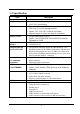
1-2 Specification Spec Description ATX form factor 4 layers PCB size: 30.5x21.0cm VIA PT800 North Bridge Chipset VIA VT8237 South Bridge Design Chipset ∗ ∗ ∗ CPU Socket ∗ Support Intel Pentium 4 478-Pin package utilizes Flip-Chip Pin Grid Array (FC-PGA2) package processor ∗ ∗ ∗ ∗ Support 1.5G∼3.2G 478 Pin Pentium 4 processor Reserves support for future Intel Pentium 4 processors 184-pin DDR module socket x3 Support 3 pcs DDR266/DDR333/DDR400 DDR Modules Expandable to 3.0GB AGP slot x1 support AGP 2.
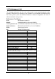
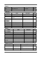
1-3 Performance List The following performance data list is the testing result of some popular benchmark testing programs. These data are just referred by users, and there is no responsibility for different testing data values gotten by users (the different Hardware & Software configuration will result in different benchmark testing results.
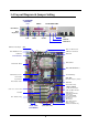
1-4 Layout Diagram & Jumper Setting (for PT800DBP/ PT800DBZ) LAN PRINT GAME/MIDI PORT PS/2 Mouse PS/2 Keyboard USB COM1 COM2 MIC LINE-IN LINE-OUT K/B Power ON Jumper (JP1) ATX 12V Power Conn. PS2 KB/Mouse Port ATX Power Connector CPU FAN USB Port/ LAN Connector CPU Socket PC99 Back Panel DDR SDRAM DIMM x3 ATX P9 Power Conn. VIA PT800 Chip CD Audio (JP2, JP4) System FAN Front Panel Audio CPU F.S.B.
Jumpers Jumper JBAT JP1 JP2, JP4 Name Description CMOS RAM Clear Keyboard Power On Enable/Disabled CPU Front Side Bus Frequency Select 3-pin Block 3-pin Block 6-pin Block Page P.6 P.7 P.
Chapter 2 Hardware installation 2-1 Pre-Hardware installation Before starting to use the computer with the motherboard installed the components on it, please make sure complete the following steps: 1. To verify the jumper settings of your motherboard 2. To install the CPU and Cooling Kits 3. To install the system memory 4. To install the expansion cards 5. To connect with ribbon cables, panel wires, and power supply 6. To setup BIOS 7.
(2) Keyboard Power On function Enabled/Disabled: JP1 When setting Enabled you can using keyboard by key in password to power on system.
2-3 To install the CPU 2-3-1 Glossary Chipset (or core logic) - two or more integrated circuits which control the interfaces between the system processor, RAM, I/O devises, and adapter cards. Processor socket - the socket used to mount the system processor on the motherboard. Slot (AGP, PCI, ISA, RAM DIMMs) - the slots used to mount adapter cards and system RAM. AGP - Accelerated Graphics Port - the high speed interface for video cards which runs at 1X (66MHz), 2X (133MHz), 4X (266MHz), and 8X (533MHz).
2-3-2 About INTEL PENTIUM 4 478-PIN CPU This motherboard provides a 478-pin surface mount, Zero Insertion Force (ZIF) socket, referred to as the mPGA478B socket supports Intel Pentium 4 processor in the 478 Pin package utilizes Flip-Chip Pin Grid Array (FC-PGA2) package technology. The CPU that comes with the motherboard should have a cooling FAN attached to prevent overheating. If this is not the case, then purchase a correct cooling FAN before you turn on your system.
DDR3 (BANK4+BANK5) DDR2 (BANK2+BANK3) DDR1 (BANK0+BANK1) Generally speaking, installing DDR SDRAM modules to your motherboard is very easy, you can refer to figure 2-4 to see what a 184-Pin PC2100/PC2700/PC3200 DDR SDRAM module looks like. Figure 2-4 NOTE! When you install DIMM modules fully into the DIMM sockets the eject tab should be locked into the DIMM modules firmly and fit to its indention on both sides. WARNING! For the DDR SDRAM CLOCK is set at 166MHz, use only PC2700- compliant DDR Modules.
2-5-2 Assigning IRQs For Expansion Card Some expansion cards need to assign an IRQ address to operate. Generally speaking, an IRQ address must exclusively assign to one use only. With standard factory design, there are 16 IRQs available, but most of them are already in use.
This motherboard provides an AGP Slot, support the 4X/8X AGP VGA card. 2x notch 4x notch AGP SLOT 2-6 Connectors and pin headers 2-6-1 Connectors (1) Power Connector (20-pin block) : ATXPWR ATX Power Supply connector. This is a new defined 20-pins connector that usually comes with ATX case. The ATX Power Supply allows to use soft power on momentary switch that connect from the front panel switch to 2-pins Power On jumper pole on the motherboard.
Pin 1 (3) ATX P9 Power Connector (6-pin block) : ATXP1 This is a new defined 6-pins connector that usually comes with ATX Power Supply. The ATX Power Supply which fully support Pentium 4 processor must including this connector for support extra 3.3V and 5V voltage to maintain system power consumption. Without this connector might cause system unstable because the power supply can not provide sufficient current for system. GND BLK GND GND 3.3V BLK 3.
(9) Serial Port COM1, COM2 : COM1, COM2 COM1, COM2 are the 9-pin D-Subminiature mail connector. The On-board serial port can be disabled through BIOS SETUP. Please refer to Chapter 3 “INTEGRATED PERIPHERALS SETUP” section for more detail information. PS/2 Mouse LAN USB PS/2 Keyboard PRINT COM1 GAME/MIDI PORT COM2 MIC LINE-IN LINE-OUT (10) Floppy drive Connector (34-pin block): FDD This connector supports the provided floppy drive ribbon cable.
IDE1 Pin 1 Primary IDE Connector (12) Secondary IDE Connector (40-pin block): IDE2 This connector connects to the next set of Master and Slave hard disks. Follow the same procedure described for the primary IDE connector. You may also configure two hard disks to be both Masters using one ribbon cable on the primary IDE connector and another ribbon cable on the secondary IDE connector. IDE2 Pin 1 Secondary IDE Connector • Two hard disks can be connected to each connector.
2-6-2 (1) Pin headers IEEE 1394A Port Header (9-pin) : 1394A/1394B (For PT800DBZ only) Note: Orient the read marking on the 1394 ribbon cable to pin 1 1394A 1394B 2 10 2 10 9 Pin 1 9 Pin 1 IEE1394A Port Header AUDIO AUD_RET_L AUD_GND AUD_VCC AUD_RET_R (2) Line-Out, MIC Header (9-pin): AUDIO This header connect to Front Panel Line-out, MIC connector with cable.
(5) Reset switch lead: RESET This 2-pin connector connects to the case-mounted reset switch for rebooting your computer without having to turn off your power switch. This is a preferred method of rebooting in order to prolong the lift of the system’s power supply. See the figure below. (6) Speaker connector: SPEAK This 4-pin connector connects to the case-mounted speaker. See the figure below. (7) Power LED: PWR LED The Power LED is light on while the system power is on.
(10) FAN Speed Headers (3-pin) : SFAN1, SYSFAN, CPUFAN These connectors support cooling fans of 350mA (4.2 Watts) or less, depending on the fan manufacturer, the wire and plug may be different. The red wire should be positive, while the black should be ground. Connect the fan’s plug to the board taking into consideration the polarity of connector.
2-7 Starting up your computer 1. After all connection are ready, close your computer case cover. 2. Be sure all the switches are off, and check that the power supply input voltage is set to proper position, usually in-put voltage is 220V∼240V or 110V∼120V depending on your country’s voltage used. 3. Connect the power supply cord into the power supply located on the back of your system case according to your system user’s manual. 4. Turn on your peripherals as following order: a. Your monitor. b.
Chapter 3 Introducing BIOS Settings The BIOS is a program located on a Flash Memory of the motherboard. Using this program as a bridge between motherboard and operating system. When the computer starting to work, the BIOS program gain control. The BIOS first operates an auto-diagnostic test called POST (power on self test) for all the necessary hardware, it detects the entire hardware device and configures the parameters of the hardware synchronization.
3-2 Getting Help Main Menu The on-line description of the highlighted setup function is displayed at the bottom of the screen. Status Page Setup Menu/Option Page Setup Menu Press F1 to pop up a small help window that describes the appropriate keys to use and the possible selections for the highlighted item. To exit the Help Window, press . 3-3 The Main Menu Once you enter Award® BIOS CMOS Setup Utility, the Main Menu (Figure 3-1) will appear on the screen.
Standard CMOS Features Use this Menu for basic system configurations. Advanced BIOS Features Use this menu to set the Advanced Features available on your system. Advanced Chipset Features Use this menu to change the values in the chipset registers and optimize your system’s performance. Integrated Peripherals Use this menu to specify your settings for integrated peripherals. Power Management Setup Use this menu to specify your settings for power management.
3-4 Standard CMOS Features The items in Standard CMOS Setup Menu are divided into several categories. Each category includes no, one or more than one setup items. Use the arrow keys to highlight the item and then use the or keys to select the value you want in each item.
Access Mode The settings are Auto Normal, Large, and LBA.
CPU Internal Cache The default value is Enabled. Enabled (default) Enable cache Disabled Disable cache Note: The internal cache is built in the processor. External Cache Choose Enabled or Disabled. This option enables the Level 2 cache memory. CPU L2 Cache Choose Enabled or Disabled. This option enables the Level 2 cache memory. Quick Power On Self-Test This category speeds up Power On Self Test (POST) after you power on the computer. set to Enabled.
Typematic Delay (Msec) Sets the delay time after the key is held down before is begins to repeat the keystroke. settings are 250, 500, 750, and 1000. The Security Option This category allows you to limit access to the system and Setup, or just to Setup. The system will not boot and access to Setup will be denied if the correct password is not entered at the prompt. System Setup (default) The system will boot, but access to Setup will be denied if the correct password is not entered prompt.
System BIOS Cacheable Selecting Enabled allows caching of the system BIOS ROM at F0000h-FFFFFh, resulting in better system performance. However, if any program writes to this memory area, a system error may result. The settings are: Enabled and Disabled. Video RAM Cacheable Select Enabled allows caching of the video BIOS, resulting in better system performance. However, if any program writes to this memory area, a system error may result. The settings are: Enabled and Disabled.
CAS Latency When synchronous DRAM is installed, the number of clock cycles of CAS latency depends on the DRAM timing. The settings are: 2T and 2.5T.
3-7 Integrated Peripherals CMOS Setup Utility – Copyright(C) 1984-2003 Award Software Integrated Peripherals > OnChip IDE Function Press Enter > OnChip Device Function Press Enter > Onboard Super IO Function Press Enter Init Display First PCI Slot Item Help Menu Level > ↑↓→← Move Enter:Select +/-/PU/PD:Value F10:Save ESC:Exit F1:General Help F5:Previous Values F6:Optimized Defaults F7:Standard Defaults OnChip IDE Function Please refer to section 3-7-1 OnChip Device Function Please refer to sect
3-7-1 OnChip IDE Function CMOS Setup Utility – Copyright(C) 1984-2003 Award Software OnChip IDE Function OnChip IDE Channel0 OnChip IDE Channel1 Primary Master PIO Primary Slave PIO Secondary Master PIO Secondary Slave PIO Primary Master UDMA Primary Slave UDMA Secondary Master UDMA Secondary Slave UDMA IDE 32-bit Transfer Mode IDE Prefetch Mode IDE HDD Block Mode Delay For HDD (Secs) Enabled Enabled Auto Auto Auto Auto Auto Auto Auto Auto Enabled Enabled Enabled 0 Item Help Menu Level >> Move Enter:S
3-7-2 OnChip Device Function CMOS Setup Utility – Copyright(C) 1984-2003 Award Software OnChip Device Function VIA 1394 Function VIA SATA Function VIA LAN Function VIA LAN Boot ROM VIA LAN BootROM Boot option VIA LAN BootROM PXERPL Option Current VIA MAC Address is VIA MAC Address Input AC97 Sound Device Game Port Address Midi Port Address Midi Port IRQ USB Host Controller USB 2.
3-7-3 Onboard Super IO Function CMOS Setup Utility – Copyright(C) 1984-2003 Award Software Onboard Super IO Function Onboard FDD Controller Enabled Onboard Serial Port 1 3F8/IRQ4 Onboard Serial Port 2 2F8/IRQ3 UART2 Mode Normal RxD, TxD Active Hi, Lo IR Duplex Mode Half Use IR Pins IRRX/IRTX Onboard Parallel Port 378/IRQ7 Parallel Mode SPP EPP Mode Select EPP1.
SPP/EPP/ECP/ECP+EPP To operate the onboard parallel port as Standard Parallel Port only, choose “SPP.” To operate the onboard parallel port in the EPP modes simultaneously, choose “EPP.” By choosing “ECP”, the onboard parallel port will operate in ECP mode only. Choosing “ECP+EPP” will allow the onboard parallel port to support both the ECP and EPP modes simultaneously. The ECP mode has to use the DMA channel, so choose the onboard parallel port with the ECP feature.
Video Off Method This determines the manner in which the monitor is blanked. DPMS (default) Blank Screen V/H SYNC+Blank Initial display power management signaling. This option only writes blanks to the video buffer. This selection will cause the system to turn off the vertical and horizontal synchronization ports and write blanks to the video buffer. Modem Use IRQ This determines the IRQ in which the MODEM can use. The settings are: 3, 4, 5, 7, 9, 10, 11, NA.
Wake-Up on RTC Alarm This function is for setting date and time for your computer to boot up. During Disabled, you cannot use this function. During Enabled, choose the Date and Time Alarm: Date(of month) Alarm You can choose which month the system will boot up. Set to 0, to boot every day. Time(hh:mm:ss) Alarm You can choose what hour, minute and second the system will boot up.
CMOS Setup Utility – Copyright(C) 1984-2003 Award Software PnP/PCI Configurations PnP OS Installed Reset Configuration Data No Disabled Resources Controlled By x IRQ Resources Item Help Manual Press Enter PCI/VGA Palette Snoop Assign IRQ For VGA Assign IRQ For USB Menu Level > Disabled Enabled Enabled Move Enter:Select +/-/PU/PD:Value F10:Save ESC:Exit F1:General Help F5:Previous Values F6:Optimized Defaults F7:Standard Defaults Reset Configuration Data Normally, you leave this field Disabled.
3-9-1 IRQ Resources CMOS Setup Utility – Copyright(C) 1984-2003 Award Software IRQ Resources IRQ3 assigned to PCI Device IRQ4 assigned to PCI Device IRQ5 assigned to PCI Device IRQ7 assigned to PCI Device IRQ9 assigned to PCI Device IRQ10 assigned to PCI Device IRQ11 assigned to PCI Device IRQ12 assigned to PCI Device IRQ14 assigned to PCI Device IRQ15 assigned to PCI Device Item Help Menu Level >> ↑↓→← Move Enter:Select +/-/PU/PD:Value F10:Save ESC:Exit F1:General Help F5:Previ
Current CPU Temperature/Current System Temp/Current FAN1, FAN2 Speed/Vcore/ Vdd/ 3.3V/+5V/+12V/-12V/VBAT(V)/5VSB(V) This will show the CPU/FAN/System voltage chart and FAN Speed. Detect CPUFAN in Post During Enabled, system will warn the user if CPU Fan is not functioning. 3-11 Miscellaneous Control This section is for setting CPU Frequency/Voltage Control.
3-12 Load Standard/Optimized Defaults Load Standard Defaults When you press on this item, you get confirmation dialog box with a message similar to: Load Standard Defaults (Y/N)? N Pressing loads the BIOS default values for the most stable, minimal-performance system operations.
Chapter 4 DRIVER & FREE PROGRAM INSTALLATION Check your package and there is A MAGIC INSTALL CD included. This CD consists of all DRIVERS you need and some free application programs and utility programs. In addition, this CD also include an auto detect software which can tell you which hardware is installed, and which DRIVERS needed so that your system can function properly. We call this auto detect software MAGIC INSTALL.
4-1 VIA 4IN1 * Install VIA Service Pack 4 IN 1 Driver The path of the file is X:\VIA\DRIVER\SETUP.EXE IDE : VIA ATAPI VENDOR SUPPORT DRIVER IS USED TO FIXED COMPATIBILITY ISSUE FOR IDE DEVICES AGPVXD : VIA AGPVXD DRIVER IS TO BE INSTALLED, IF YOU ARE USING AN AGP VGA CARD, VIAGART.
5. Click NEXT to Install ATAPI Vender 6. Click NEXT to choose enabled DMA Mode 8. Click NEXT to Install VIA IRQ Routing Support Driver 7. Click NEXT to Install VIA AGP VXD Driver 9.
4-2 SOUND install ALC AC97’ Codec Audio Driver 1. Click SOUND when MAGIC INSTALL MENU appears 2. Then auto detect operation system language edition, click OK, start to install DRIVER 3. Click Finish and Restart Windows 4. Click Start→Program→Avance Sound Manager→AvRack. Then AVRACK Windows appears 5. Sound Effect select and KaraOK Mode Function 6.
7. 2/4/6 channel speaker configuration setting Note: The path of the file 8. 6 channel speaker place test For WIN98/NT4.0/WIN2K/XP is X:\CODEC\ALC\SETUP.EXE Note: In Win2K/WinME users have to click Control Panel\System\Device Manager\ DVD\CD-ROM drives to Enabled digital CD Audio for the CD-ROM Device when use the SPDIF-Out digital signal. 4-3 LAN Install VIA LAN Controller Driver (PT800DBP/PT800DBZ) The VIA 10/100Mb PCI Ethernet Adapter Driver path is X:\VIA\LANDRV 1.
4-4 PC-HEALTH Winbond Hardware Doctor Monitoring Software The path of the file is X:\VIA\HEALTH-W\SETUP.EXE (Only support WINDOWS 95/98/98SE/ME) In Windows 95/98 Winbond Hardware Doctor Monitoring Software needs some system files to copy in Utility that’s why it needs install PC-HEALTH twice to complete setup. 1. Click PC-Health when Magic Install Menu appears 2. Click OK when Winbond Hardware Doctor Setup Window appears 3. Click the Button to start installation 4.
4-5 MAGIC BIOS Install BIOS Live Update Utility 1. Click Magic BIOS when Magic Install MENU appears 2. Click Next to install the Magic BIOS in Destination Folder 3. After finish Setup you will have a Magic BIOS icon in your screen 4. Double click the Magic BIOS icon you will have this picture, choose from internet you can upgrade BIOS On-line 5. When On-line update BIOS the program will 6.
9. 4-6 When choose From Local Driver to update BIOS, you must have the correct BIOS file in your Local Driver 10. Choose the correct BIOS file to update BIOS PC-CILLIN Install PC-CILLIN 2002 Anti-virus program 1. Click PC-CILLIN when MAGIC INSTALL 2. (1) Click "Install PC-CILLIN" when MENU appear PC-CILLIN 2002 main menu appears, and Click NEXT when "Install Shield Wizard For PC-CILLIN 2002" (2) Click Open Manual. you can learn PC-CILLIN 2002 how to use 3.
5. Click INSTALL, Start to install the software 6. Setup Complete and click FINISH 7. After PC-CILLIN 2002 complete, Please 8. finish register process, we recommend select register your information and get LICENSE update item to download newest engine code KEY from TREND MICRO web site, enter and virus code your license key and click FINISH Note : Please install ACROBAT READER, Before you read PC-CILLIN 2002 User Manual, the path at X:\acrobat\ar500eng.exe 4-7 USB2.0 Install VIA USB2.
3. Select Install USB Driver and Click NEXT 4. Select FINISH and Restart your Computer 5. Check device working properly in Device Manager The Path of the file is X:\VIA\VIAUSB20\SETUP.EXE 4-8 SATA Install VIA Serial ATA 1. Click SATA when MAGIC INSTALL MENU appears 2. Start install VIA serial ATA driver , then click NEXT 3. When license agreement appear, choose I agree and click NEXT 4.
5. Review install driver and utility component, 6. Click FINISH and restart your computer then click NEXT 4-9 HOW TO DISABLE ON-BOARD SOUND Enter BIOS SETUP choose INTEGRATE PERIPHERALS choose ON-CHIP DEVICE FUNCTION choose AC97 SOUND DEVICE Disable on-board sound function by press PAGE DOWN KEY to Disable 4-8 HOW TO DISABLE ON-BOARD SOUND 4-10 HOW TO UPDATE BIOS Method 1. Method 2. Use “Magic BIOS” update BIOS in Windows 98 (refer page 46) In DOS Mode STEP 1. Prepare a boot disc.