Intel® Server Board SE7500CW2 Product Guide A Guide for Technically Qualified Assemblers of Intel® Identified Subassemblies/Products Order Number: A86513-003
Disclaimer Information in this document is provided in connection with Intel® products. No license, express or implied, by estoppel or otherwise, to any intellectual property rights is granted by this document.
Contents 1 Description Server Board Features ......................................................................................................... 7 Back Panel Connectors ............................................................................................... 9 Server Board Connector and Component Locations ...................................................10 Processor ...................................................................................................................
Installation Procedures ........................................................................................................50 Installing the I/O Gasket and Shield ............................................................................50 Configuring Chassis Standoffs....................................................................................52 Installing Rubber Bumpers..........................................................................................53 Installing the Server Board....
6 Getting Help ...................................................................................................................83 7 Technical Reference Configuration Jumpers ........................................................................................................85 Front Panel Header .............................................................................................................86 8 Regulatory and Integration Information Product Regulatory Compliance .........................
28. 29. 30. 31. 32. Attaching the Heat Sink Fan .......................................................................................71 Attaching Intake and Exhaust Assemblies ..................................................................71 Replacing the Backup Battery.....................................................................................73 Configuration Jumper Location ...................................................................................
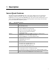
1 Description Server Board Features The Intel® Server Board SE7500CW2 offers a “flat” design, with the processors and memory subsystems residing on the board. The server board supports dual-processor operation with Intel® Xeon™ processors and the Intel® E7500 chipset. The board contains embedded devices for video, network, and IDE and provides basic monitoring hardware and interrupt control for dual processors and PC/AT†-compatible operation. Table 1.
Table 1. Server Board Features (continued) Feature Description System I/O Winbond† W83627HF Super I/O Controller (Low Pin Count [LPC] bus) that provides the following: • Hardware monitoring • PS/2†-compatible keyboard and mouse ports, 6-pin DIN • Advanced parallel port, supporting Enhanced Parallel Port (EPP) level 1.7 and 1.
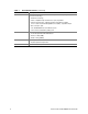
DIMM Memory Connector 3B DIMM Memory Connector 3A DIMM Memory Connector 2B DIMM Memory Connector 2A Main Power Aux. Pwr Back Panel Connectors USB E A B C D F G OM14419 A. B. C. D. E. F. G. USB 1, 2, 3 Keyboard/mouse Serial port 1 Video Parallel NIC1 NIC2 Figure 1.
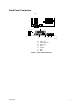
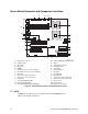
Server Board Connector and Component Locations A B C D E USB Main Power Aux. Pwr DIMM Memory Connector 3B DIMM Memory Connector 3A DIMM Memory Connector 2B DIMM Memory Connector 2A BB F AA Z Y G H I J K X W V L U M N O T S R Q P OM14279A A. B. C. D. E. F. G. H. I. J. K. L. M. N.
Processor The Server Board SE7500CW2 accommodates two Intel Xeon processors with 512 KB cache. The SKT604 is a 604-pin zero-insertion force (ZIF) socket. The processor(s) interface with the system bus at 400 MHz. For a complete list of supported processors, see: http://support.intel.com/support/motherboards/server/SE7500CW2 Dual Processor Operation The Intel Xeon interface is dual processor (DP) ready.
Intel® E7500 Chipset The Server Board SE7500CW2 includes an Intel E7500 chipset (MCH, ICH3, P64H2) that provides an integrated I/O bridge and memory controller and a flexible I/O subsystem core (PCI). MCH The MCH North Bridge in the E7500 chipset integrates three main functions: • An integrated high-performance main memory subsystem • An HI 2.0 bus interface that provides a high-performance data flow path between the host bus and the I/O subsystem • A HI 1.
Super I/O The Server Board SE7500CW2 uses the Winbond W83627HF Super I/O Plug and Play Compatible with ACPI-Compliant Controller/Extender. This device provides the system with the following: • Two serial ports • One parallel port • Floppy disk controller • PS/2-compatible keyboard and mouse controller • Two ATA 100 IDE channels • HW monitor controller The Server Board SE7500CW2 provides the connector interface for the floppy disk drive, dual serial ports, parallel port, PS/2 mouse, and PS/2 keyboard.
Memory The Server Board SE7500CW2 contains four 184-pin DIMM sockets and provides up to 4 GB of memory. Memory is partitioned as two banks of DDR DIMMs, each of which provides 144 bits of two-way interleaved memory. The Server Board SE7500CW2 supports up to four ECC DDR DIMMs that are compliant with the JEDEC DDR 200/266 specification.
64-bit / 133 MHz PCI-X Capable Subsystem The 64-bit/133 MHz PCI segment includes one 3.3 V keyed PCI expansion slot that can support PCI-X add-in cards up to 133 MHz and are backward compatible to 64 bit/66 MHz, 64 bit/33 MHz, and 32 bit/33 MHz PCI cards. 64-bit/133 MHz PCI features include: • Bus speed up to 133 MHz • 3.
32-bit/33 MHz PCI Subsystem The 32-bit/33 MHz PCI segment includes the following embedded devices and connectors: • Two 5 V keyed PCI expansion slots • Integrated Intel EtherExpress PRO100+ 10/100 megabit PCI Ethernet controller (Intel 82550PM) • Integrated ATI Rage XL video controller with 8 MB of on-board SDRAM • Integrated Promise PDC20267 ATA-100 RAID controller 32-bit/33 MHz PCI features include: • Bus speed up to 33 MHz • 5 V signaling environment • Burst transfers up to a peak of 132 MB/s • 8-, 16-,
ACPI The Advance Configuration and Power Interface (ACPI)–aware operating system can place the system into a state where the hard drives spin-down, the system fans stop, and all processing is halted. In this state the power supply is still on and the processors still dissipate some power, so the power supply fan and processor fans are still running. ✏ NOTE ACPI requires an operating system that supports this feature. The Server Board SE7500CW2 supports sleep states S0, S4, and S5.
Security The Server Board SE7500CW2 BIOS provides the ability to secure itself. Table 2 summarizes the security options available in the BIOS. Table 2. Mode User Password on boot (AT style) Security Operation Summary Entry Method/ Event Entry Criteria Power On/Reset User password set and password on boot enabled Behavior Exit Criteria After Exit System halts for User Password before booting. The system is not in secure mode. Except for the password, no mouse or keyboard input is accepted.
Using Passwords If only the supervisor password is set, you: • Must enter the supervisor password to enter BIOS Setup. • Must enter the supervisor password to boot the server if Password on Boot is enabled in the BIOS Setup. • Must enter the supervisor password to exit secure mode. If both passwords are set, you: • May enter the user password to enter BIOS Setup. However, you will not be able to change many of the options.
Intel Server Board SE7500CW2 Product Guide
2 Configuration Software and Utilities This chapter describes the Power-On Self-Test (POST) and server configuration utilities. Table 3 below briefly describes the utilities. Table 3. Configuration Utilities Utility Description and brief procedure Page BIOS Setup If the system does not have a diskette drive or the drive is disabled or misconfigured, use BIOS Setup to enable it.
Using BIOS Setup Utility This section describes the BIOS Setup Utility options. Use BIOS Setup to change the server configuration defaults. You can run BIOS Setup with or without an operating system being present. If You Cannot Access Setup If the diskette drive is misconfigured so that you cannot access it to run a utility from a diskette, you may need to clear CMOS memory.
Table 4. Keyboard Commands Press Description Help - Pressing F1 on any menu invokes the general Help window. ←→ The left and right arrow keys are used to move between the major menu pages. The keys have no affect if a submenu or pick list is displayed. ↑ Select Item up - The up arrow is used to select the previous value in a menu item’s option list, or a value field pick list. Pressing the Enter key activates the selected item.
Table 5 describes the on-screen options you will see in BIOS Setup and what they mean. Table 5. On-Screen Options When you see this: What it means: On screen, an option is shown but you cannot select it or move to that field. You cannot change or configure the option in that menu screen. Either the option is auto-configured or auto-detected, or you must use a different Setup screen. Press to display a submenu that is either a separate full screen menu or a popup menu with one or more choices.
Main Menu To access this menu, select Main on the menu bar at the top of the screen. Advanced Main Security Power Boot System Exit Primary Master Primary Slave Secondary Master Secondary Slave Table 7 lists the options available on the Main menu. This menu allocates resources for hardware components. Table 7.
Primary/Secondary, Master/Slave Submenus To access this submenu, select Main on the menu bar at the top of the screen and then the master or slave to be configured. Advanced Main Security Power Boot System Exit Primary Master Primary Slave Secondary Master Secondary Slave There are four IDE submenus: primary master, primary slave, secondary master, and secondary slave. Table 8 shows the format of the IDE submenus. For brevity, only one example is shown. Table 8.
Advanced Menu To access this menu, select Advanced on the menu bar at the top of the screen. Main Advanced Security Power Boot System Exit I/O Device Configuration On Board Device PCI Configuration Server Menu Console Redirection Event Logging Hardware Monitor Table 9 list the selections available on the Advanced menu. This menu configures advanced features available through the chipset. Table 9.
Table 9. Advanced Menu (continued) Feature Choices Description Boot-time Diagnostic Screen • Enabled Enables or disables the boot-time diagnostic screen. • Disabled (default) Disabled will display the splash screen over the diagnostic screen. This splash screen can be changed to show an OEM-based logo. Reset Configuration Data • No (default) Specifies if the extended server configuration data will be reset during the next boot.
I/O Device Configuration Submenu To access this submenu, select Advanced on the menu bar at the top of the screen and then I/O Device Configuration. Main Security Power Advanced I/O Device Configuration Boot System Exit On Board Device PCI Configuration Server Menu Console Redirection Event Logging Hardware Monitor Table 10 lists the options available through the I/O Device Configuration submenu. This submenu configures the I/O ports on the board. Table 10.
Table 10. I/O Device Configuration Submenu (continued) Feature Choices Description Mode (This feature is present only when Parallel Port is set to Enabled) • Output only Sets the mode for the parallel port. • Bi-directional Output only is the standard printer connection mode. • EPP Bi-directional is the standard bidirectional mode. • ECP (default) EPP is Enhanced Parallel Port mode, a high-speed bidirectional mode. Selection based on what EPP version the printer supports.
On Board Device Submenu To access this submenu, select Advanced on the menu bar at the top of the screen and then On Board Device. Main Advanced Security Power Boot System Exit I/O Device Configuration On Board Device PCI Configuration Server Menu Console Redirection Event Logging Hardware Monitor Table 11 lists the options available through the On Board Device submenu. This submenu configures the RAID, network, and USB controllers on the board. Table 11.
PCI Configuration Submenu To access this submenu, select Advanced on the menu bar at the top of the screen and then PCI Configuration. Main Advanced Security Power Boot System Exit I/O Device Configuration On Board Device PCI Configuration Onboard RAID PCI Device, Slot #1 PCI Device, Slot #2 PCI Device, Slot #3 PCI Device, Slot #4 PCI Device, Slot #5 Server Menu Console Redirection Event Logging Hardware Monitor Table 12 lists the options available through the PCI Configuration submenu.
Table 13 lists the options available on the Option ROM Scan submenu. This submenu appears for each of the options available on the Advanced PCI Configuration submenu above (see Table 12). For brevity, only one example is shown. Table 13. Option ROM Scan Submenu Feature Choices Description Option ROM Scan • Enabled (default) Initializes the device expansion ROM. • Disabled Server Menu Submenu To access this submenu, select Advanced on the menu bar at the top of the screen and then Server Menu.
Console Redirection Submenu To access this submenu, select Advanced on the menu bar at the top of the screen and then Console Redirection. Main Security Advanced Power Boot System Exit I/O Device Configuration On Board Device PCI Configuration Server Menu Console Redirection Event Logging Hardware Monitor Table 15 lists the options available through the Console Redirection submenu. This submenu provides additional options to configure the console. Table 15.
Event Logging Submenu To access this submenu, select Advanced on the menu bar at the top of the screen and then Event Logging. Main Advanced Security Power Boot System Exit I/O Device Configuration On Board Device PCI Configuration Server Menu Console Redirection Event Logging Hardware Monitor Table 16 lists the options available through the Event Logging submenu. This submenu allows you to view the event logs. Table 16.
Hardware Monitor Submenu To access this submenu, select Advanced on the menu bar at the top of the screen and then Hardware Monitor. Main Advanced Security Power Boot System Exit I/O Device Configuration On Board Device PCI Configuration Server Menu Console Redirection Event Logging Hardware Monitor Table 17 lists the settings displayed in the Hardware Monitor submenu.
Security Menu To access this menu, select Security on the menu bar at the top of the screen. Main Advanced Security Power Boot System Exit Table 18 lists the options available on the Security menu. Enabling the Supervisor Password field requires a password for entering Setup. The passwords are not case-sensitive. Table 18. Security Menu If no password entered previously: Feature Choices Description Set User Password The user password controls access to the system at boot.
Power Menu To access this menu, select Power on the menu bar at the top of the screen. Main Advanced Security Power Boot System Exit Table 19 lists the options available on the Power menu. This menu is designed to disable ACPI automatic reboot in the S0 or S4 states. If these submenus are enabled and AC power is lost, the server power and its operating system will remain off. Table 19.
Table 20. Boot Menu Boot Priority st 1 Boot Device nd 2 Boot Device rd 3 Boot Device th 4 Boot Device Device Description • Removable Devices Specifies the boot sequence according to the device type. The computer will attempt to boot from up to four devices as specified here. Only one of the devices can be an IDE hard disk drive.
System Menu To access this menu, select System on the menu bar at the top of the screen. Main Advanced Security Power Boot System Exit Table 21 lists the options available on the System menu. This menu displays information on vendor, processor, memory, peripherals, and BIOS. Table 21. System Menu Feature Choices Description Machine Vendor Provides basic information on the machine vendor: • Manufacturer: Intel Corporation • Product: SE7500CW2 • Version: 1.
Table 21. System Menu (continued) Feature Choices Description Peripherals Provides the port connectors for onboard designators.
Upgrading the BIOS Preparing for the Upgrade Before you upgrade the BIOS, prepare for the upgrade by recording the current BIOS settings, obtaining the upgrade utility, and making a copy of the current BIOS. Recording the Current BIOS Settings 1. Boot the computer and press when you see the message: Press Key if you want to run SETUP 2. Write down the current settings in the BIOS Setup program. ✏ NOTE Do not skip step 2.
Creating the BIOS Upgrade Diskette The BIOS upgrade file is a compressed self-extracting archive that contains the files you need to upgrade the BIOS. 1. Insert the bootable diskette into the diskette drive. 2. Extract the contents of the BIOS.EXE file onto the bootable diskette. To do so, simply type the file name (with or without the extension) at the a:\ prompt, for example “BIOS.EXE.” 3. You will be prompted to confirm a folder in which to store the extracted files.
1. Obtain the BIOS update file package from http://support.intel.com. 2. A file called “crisis.zip” is one of the files included with each Server Board SE7500CW2 BIOS release file package. Unzip the “crisis.zip” file to a directory on your hard drive. 3. Format a blank diskette (the diskette should not be a bootable DOS diskette). Insert the diskette into the diskette drive. 4. From the MS-DOS† prompt on an MS-DOS system, run the “crisdisk.bat” file from the directory you created on your hard drive.
Hardware Monitoring The Server Board SE7500CW2 has an integrated Winbond Heceta† 836327HF chip that is responsible for hardware monitoring. Together, the Winbond Heceta chip and Intel® LANDesk® Client Manager (LDCM) 6.3 software provide basic server hardware monitoring that alerts a system administrator if a hardware problem occurs on an Intel Server Board SE7500CW2–based system. The Intel LDCM software is for use with Windows 2000 Server and Windows 2000 Advanced Server operating systems.
Intel Server Board SE7500CW2 Product Guide
3 Server Board Installation Tools and Supplies Needed • • • • • Phillips† (cross head) screwdriver (#1 bit and #2 bit) Needle nosed pliers A ruler Pen or pencil Antistatic wrist strap and conductive foam pad (recommended) Before You Begin Emissions Disclaimer To ensure EMC compliance with your local regional rules and regulations, the final configuration of your end system product may require additional EMC compliance testing. For more information please contact your local Intel Representative.
ESD and handling boards: Always handle boards carefully. They can be extremely sensitive to ESD. Hold boards only by their edges. After removing a board from its protective wrapper or from the server, place the board component side up on a grounded, static free surface. Use a conductive foam pad if available but not the board wrapper. Do not slide board over any surface. Installing or removing jumpers: A jumper is a small plastic encased conductor that slips over two jumper pins.
Minimum Hardware Requirements To avoid integration difficulties and possible board damage, your system must meet the following minimum requirements. For a list of qualified memory and chassis components see: http://support.intel.com/support/motherboards/server/SE7500CW2 Processor Minimum of one 1.8 GHz Intel Xeon processor with 512K cache support. For a complete list of supported processors, see: http://support.intel.
Installation Procedures Installing the I/O Gasket and Shield ✏ NOTE An ATX 2.03-compliant I/O shield is provided with the server board. The shield is required by Electromagnetic Interference (EMI) regulations to minimize EMI. If the shield does not fit the chassis, obtain a properly sized shield from the chassis supplier. The shield fits the rectangular opening in the back of a chassis. The shield has cutouts that match the I/O ports. Install the shield from inside the chassis.
Attaching the Label to the I/O Shield 1. Remove the backing from the label included with your server board. 2. Press the label onto the outside face of the I/O shield. See Figure 4, A. US B 1 2 3 MO US E KY BD PA RA LL EL 10/1NET 00 MB A OM14360 Figure 4. Attaching the Label to the I/O Shield Installing the I/O Shield 1. Position one edge so that the dotted groove is outside the chassis wall, and the lip of the shield rests on the inner chassis wall. 2.
Configuring Chassis Standoffs If your chassis does not have standoffs placed as shown below, you must rearrange them so they match the holes in the server board. Failure to properly rearrange the metal standoffs may cause the server board to malfunction and may permanently damage it. Your chassis may be different from the illustration. For the Intel® Server Chassis SC5200: 1. Chassis comes with positions 1, 4, 6, 20, 23, and 26 preinstalled. 2.
Installing Rubber Bumpers For the Server Chassis SC5200: 1. Measure and mark the bumper placement locations in your chassis by placing your ruler against the standoffs as shown below. 2. Remove the backing from the bumpers and press firmly into position. Rubber bumpers are included with your chassis. 1 4 8" (20.3 cm) 8 7 20 P P P P P P P 18 7 P 0 23 3 S 0 6 19 26 3" (7.6 cm) OM14425 Figure 7.
Installing the Server Board Placing the Server Board into the Chassis When placing the board into the chassis, carefully position the board’s I/O connectors into the openings in the I/O shield on the back of the chassis. 1 OM14200 Figure 8. Placing the Server Board in the Chassis Attaching the Server Board Using the screws that came with your chassis, mount the board to the chassis. USB Main Power Aux.
Installing Memory The server board supports only DDR 200/266 compliant DIMMs. Install from 256 MB to 4 GB of memory, using up to four DIMMs. DIMMs must be installed in pairs. The furthest DIMM pair from the MCH must be populated first. No DIMM mixing is allowed within a bank. Between banks only the DIMM size may be different. All DIMMs must be the same speed and architecture. For a list of supported memory, visit the Intel Support Web site: http://support.intel.
Installing the Processor(s) CAUTION If you are installing only one processor, it must be installed in the Primary Processor Socket, which is the closest to the corner of the server board. If you are installing a second processor to your system, you must verify that the second processor is identical to the first processor, same voltage and speed. Using unidentical processors could cause system failure. Installing the Retention Brackets 1.
Attaching the Processor ✏ NOTE This server board has “zero-insertion-force” sockets. If the processor does not drop easily into the socket holes, make sure the lever is in the full upright position and the processor is oriented properly. 1. Lift the socket lever on the processor. A B OM14473 Figure 12. Opening Socket Lever and Attaching Processor 2. Align the Alignment Triangle Mark (Figure 12, A) on the processor with the Alignment Triangle Cutout on the socket (Figure 12, B). 3.
Attaching the Heat Sink 1. Align the heat sink with the retention brackets and place the heat sink on the processor. 1 3 3 OM14474 Figure 14. Attaching the Heat Sink 2. Position the retention clip over the plastic tab and engage the clip end-slot over the plastic tab. 3. Press downward on the retention clip ends until they engage the plastic tabs.
Attaching the Heat Sink Fan Attach the fan to the wind tunnel air intake section as shown in Figure 16. The fan label (Figure 16, A) must point into the air intake section. A OM14476 Figure 16. Attaching the Heat Sink Fan Attaching Intake and Exhaust Assemblies ✏ NOTE System airflow should be from front to back. Make sure the wind tunnel is aligned so the fan is toward the front of the chassis and the airflow is toward the I/O shield. If two processors are installed, the fans should be side by side.
Installing the Optional SCSI Add-in Card Certain versions of the Server Board SE7500CW2 ship with an Ultra160 SCSI card. This card has the following features: • Ultra160 single channel based on the LSI† 53C1000 SCSI controller • PCI 2.
Making Connections to the Server Board C A B D E F O N G M H K L J I A T A 1 0 0 A T A 1 0 0 R A I D OM14422A A. B. C. D. E. F. G. H. Main power Auxiliary signal +12 V CPU power CPU fan 1 CPU fan 2 Front chassis fans Front panel ATA 100 IDE I. J. K. L. M. N. O. ATA 100 RAID IDE Floppy Front panel USB Chassis intrusion I2C Rear chassis fans Jumper block Figure 18.
Cable Routing To ensure proper airflow within the chassis, follow the cable routing guidelines below. If you purchased the optional SCSI hot-swap drive bay accessory, see the installation manual that shipped with the drive bay kit for information on SCSI cable routing. IDE Cables IDE cables that connect to devices in the lower device bays should be routed around the EPAC as shown below. 1. Remove the top half of the EPAC. 2. Route cables as shown in Figure 19. 3. Replace the top half of the EPAC.
Floppy Drive Cable Route the floppy drive cable as shown in Figure 20, A. A OM14421 Figure 20.
Finishing Up WARNING An electrical shock hazard exists if the chassis cover is not replaced before connecting the chassis to the main power. 1. 2. 3. 4. Install the chassis cover according to the instructions for your chassis. See your chassis documentation to complete rack or pedestal installation. Connect the keyboard, mouse and monitor cables to the back panel. Connect the power cable to the back panel and to an AC outlet. A C E D B G F I H OM14424 A. AC Power B. USB 1, 2, and 3 C. Mouse D.
4 Upgrading Tools and Supplies Needed • • • • Phillips (cross head) screwdriver (#1 bit and #2 bit) Jumper removal tool or needle nosed pliers Pen or pencil Antistatic wrist strap and conductive foam pad (recommended) Cautions These warnings and cautions apply throughout this chapter. Only a technically qualified person should configure the server board. CAUTIONS System power on/off: The power button DOES NOT turn off the system AC power.
Installing or removing jumpers: A jumper is a small plastic encased conductor that slips over two jumper pins. Some jumpers have a small tab on top that you can grip with your fingertips or with a pair of fine needle nosed pliers. If your jumpers do not have such a tab, take care when using needle nosed pliers to remove or install a jumper; grip the narrow sides of the jumper with the pliers, never the wide sides.
Processors WARNING If the server has been running, any installed processor and heat sink on the processor board(s) will be hot. To avoid the possibility of a burn, be careful when removing or installing server board components that are located near processors. CAUTIONS Processor must be appropriate: You may damage the server board if you install a processor that is inappropriate for your server. Make sure your server can handle a newer, faster processor (thermal and power considerations).
Adding or Replacing a Processor CAUTION If you are installing only one processor, it must be installed in the Primary Processor Socket, which is the closest to the corner of the server board. If you are installing a second processor to your system, you must verify that the second processor is identical to the first processor, same voltage and speed. Using unidentical processors could cause system failure. Installing the Retention Brackets 1.
Attaching the Processor ✏ NOTE This server board has “zero-insertion-force” sockets. If the processor does not drop easily into the socket holes, make sure the lever is in the full upright position and the processor is oriented properly. 1. Lift the socket lever on the processor. A B OM14473 Figure 24. Opening Socket Lever and Attaching Processor 2. Align the Alignment Triangle Mark (Figure 24, A) on the processor with the Alignment Triangle Cutout on the socket (Figure 24, B). 3.
Attaching the Heat Sink 1. Align the heat sink with the retention brackets and place the heat sink on the processor. 1 3 3 OM14474 Figure 26. Attaching the Heat Sink 2. Position the retention clip over the plastic tab and engage the clip end-slot over the plastic tab. 3. Press downward on the retention clip ends until they engage the plastic tabs.
Attaching the Heat Sink Fan Attach the fan to the wind tunnel air intake section as shown in Figure 28. The fan label (Figure 28, A) must point into the air intake section. A OM14476 Figure 28. Attaching the Heat Sink Fan Attaching Intake and Exhaust Assemblies ✏ NOTE System airflow should be from front to back. Make sure the wind tunnel is aligned so the fan is toward the front of the chassis and the airflow is toward the I/O shield. If two processors are installed, the fans should be side by side.
Removing a Processor 1. Observe the safety and ESD precautions at the beginning of this chapter and the additional cautions given here. 2. Unplug the processor fan cable from the server board. 3. Detach the processor fan from the processor wind tunnel assembly. 4. Remove the both ends of the processor wind tunnel assembly. 5. Remove the center section of the processor wind tunnel assembly. 6. Remove the heat sink from the processor. 7. Raise the socket lever on the socket. 8.
VARNING Explosionsfara vid felaktigt batteribyte. Använd samma batterityp eller en ekvivalent typ som rekommenderas av apparattillverkaren. Kassera använt batteri enligt fabrikantens instruktion. VAROITUS Paristo voi räjähtää, jos se on virheellisesti asennettu. Vaihda paristo ainoastaan laitevalmistajan suosittelemaan tyyppiin. Hävitä käytetty paristo valmistajan ohjeiden mukaisesti. 1. Observe the safety and ESD precautions at the beginning of this chapter. 2. Open the chassis. 3.
Intel Server Board SE7500CW2 Product Guide
5 Solving Problems This chapter helps you identify and solve problems that might occur while you are using the system. Resetting the System To do this: Press: Soft boot reset, which clears system memory and reloads the operating system. Clear system memory, restart POST, and reload the operating system. Reset button Cold boot reset. Turn the system power off and then on. This clears system memory, restarts POST, reloads the operating system, and halts power to all peripherals.
Running New Application Software Problems that occur when you run new application software are usually related to the software. Faulty equipment is much less likely, especially if other software runs correctly. Checklist q Does the system meet the minimum hardware requirements for the software? See the software documentation. q Is the software an authorized copy? If not, get one; unauthorized copies often do not work.
✏ NOTE Random errors in data files: If you are getting random errors in your data files, they may be getting corrupted by voltage spikes on your power line. If you are experiencing any of the above symptoms that might indicate voltage spikes on the power line, you may want to install a surge suppressor between the power outlet and the system power cord. More Problem Solving Procedures This section provides a more detailed approach to identifying a problem and locating its source.
Verifying Proper Operation of Key System Lights As POST determines the system configuration, it tests for the presence of each mass storage device installed in the system. As each device is checked, its activity light should turn on briefly. Check for the following: q Does the diskette drive activity light turn on briefly? If not, see “Diskette Drive Activity Light Does Not Light” on page 80.
No Characters Appear on Screen Check the following: q Is the keyboard functioning? Check to see that the “Num Lock” light is functioning. q Is the video monitor plugged in and turned on? q Are the brightness and contrast controls on the video monitor properly adjusted? q Are the video monitor switch settings correct? q Is the video monitor signal cable properly installed? q Is the onboard video controller enabled? If you are using an add-in video controller board, do the following: 1.
System Cooling Fans Do Not Rotate Properly If the system cooling fans are not operating properly, system components could be damaged.
Hard Disk Drive Activity Light Does Not Light The hard disk drive activity light is not connected to the Server Board SE7500CW2 front panel.
q Try reseating the add-in adapter. The add-in adapter stopped working without apparent cause. q Try reseating the adapter first; then try a different slot if necessary. q The network driver files may be corrupt or deleted. Delete and then reinstall the drivers. q Run the diagnostics. PCI Installation Tips Some common PCI tips are listed here. q Certain drivers may require interrupts that are not shared with other PCI drivers.
6 Getting Help World Wide Web http://support.intel.com/support/motherboards/server/SE7500CW2 Telephone All calls are billed US $25.00 per incident, levied in local currency at the applicable credit card exchange rate plus applicable taxes. (Intel reserves the right to change the pricing for telephone support at any time without notice). In U.S.
Intel Server Board SE7500CW2 Product Guide
7 Technical Reference Configuration Jumpers Main Power 10 9 8 7 6 5 4 3 2 1 J106 OM14430 Figure 31. Configuration Jumper Location Table 24. Configuration Jumper (J106) Jumper Name Pins What happens at system reset BIOS Recovery 1-2 If these pins are jumpered, the system will attempt BIOS recovery. These pins should not be jumpered for normal operation. Password Clear 3-4 If these pins are jumpered, the password will be cleared on the next reset.
Front Panel Header The front panel header provides connection to the front panel for power switching and LED operation. A B C E D 1 2 33 34 F G OM14434 A. Sleep Switch B. Reset Switch C. Power Switch D. HDD LED E. Power LED F. NIC 2 LED G. NIC 1 LED Figure 32. Front Panel Header Connection Location Table 25.
8 Regulatory and Integration Information Product Regulatory Compliance Product Safety Compliance The Server Board SE7500CW2 complies with the following safety requirements: • UL 1950 - CSA 950 (US/Canada) • EN 60 950 (European Union) • IEC60 950 (International) • CE – Low Voltage Directive (73/23/EEC) (European Union) • EMKO-TSE (74-SEC) 207/94 (Nordics) • GOST R 50377-92 (Russia) Product EMC Compliance The Server Board SE7500CW2 has been has been tested and verified to comply with the following electromag
Product Regulatory Compliance Markings This product is marked with the following Product Certification Markings: Table 26. Product Certification Markings UL Recognition Mark CE Mark Russian GOST Mark Australian C-Tick Mark BSMI DOC Marking BSMI EMC Warning RRL MIC Mark Electromagnetic Compatibility Notices FCC (USA) This device complies with Part 15 of the FCC Rules.
This equipment has been tested and found to comply with the limits for a Class A digital device, pursuant to Part 15 of the FCC Rules. These limits are designed to provide reasonable protection against harmful interference in a residential installation. This equipment generates, uses, and can radiate radio frequency energy and, if not installed and used in accordance with the instructions, may cause harmful interference to radio communications.
Korean RRL Compliance This product has been tested and complies with MIC Notices No. 1997-41 and 1997-42. The product has been marked with the MIC logo to illustrate compliance. The English translation for the above is as follows: 1. Type of Equipment (Model Name): SE7500CW2 2. Certification No.: Contact Intel Representative 3. Name of Certification Recipient: Intel 4. Date of Manufacturer: Marked on Product 5.
Index A D-F ACPI, 17 APIC, 12 ATI Rage IIC, 16 audible beep error codes, 21 Back Panel Connectors, 9 battery disposing of safely, 72 installing, 73 removing, 72 beep codes, 21 BIOS, 13, 16, 17, 18, 44, 45 changing the language, 45 recovering, 44 upgrading, 42, 44 bootable media, required by POST, 21 booting cold, 75 Bridge, 7 diagnostics, preparing system for testing, 77 DIMM, 14 diskette reconfiguring if cannot enter Setup, 22 running SCU from, 21 ECC, 14 ESD add-in boards, 48, 65 avoiding damage to pr
L-N language, changing in BIOS, 45 lithium backup battery disposing of safely, 72 installing, 73 removing, 72 LPC, 12 memory, 14 amount tested, POST, 21 capacity, 7 video amount, 7 what type to install, 7 network, controller, 7, 16 North Bridge, 7, 12 NVRAM, 41 P password, 18, 19 administrator, 19 PCI embedded devices, 7 expansion slots, 7 POST, 45 bootable media required, 21 memory, amount tested, 21 Power management, 12 Power-on Self-Test, See POST, 45 problems after running new application software, 76