P3 Series Intel P35/P31 Socket LGA775 Processor Mainboard User’s Manual Rev: 1.
Disclaimer The intellectual property of this manual belongs to our company. The ownership of all of the products, including accessories and software etc. belong to our company. No one is permitted to copy, change, or translate without our written permission. We compiled this manual based on our careful attitude, but we can not guarantee the accuracy of the contents.
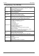
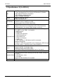
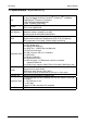
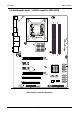
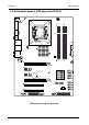
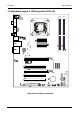
Table of Contents Chapter 1 Introduction .................................................................... 3 1.1 Package Checklist .......................................................................................... 3 1.2 Specifications ................................................................................................. 4 1.3 Mainboard Layout .......................................................................................... 7 1.4 Connecting Rear Panel I/O Devices .............
Chapter 1 Introduction 1.1 Package Checklist Thank you for choosing our product. Please check the following packing and accessories, if there is any broken or part missing, Please contact with your franchiser.
P3 Series User's Manual 1.
P3 Series User's Manual 1.
P3 Series User's Manual 1.
P3 Series User's Manual 1.
P3 Series User's Manual 1.
P3 Series User's Manual 1.
P3 Series User's Manual 1.
P3 Series User's Manual 1.4 Connecting Rear Panel I/O Devices • PS/2 Mouse: Connect to PS/2 mouse. • PS/2 Keyboard: Connect to PS/2 keyboard. • COM: Connect to external model, mouse or other devices that support this communication protocol. • Debug LED: Display error code. (please reference appendix 1) • SPDIF IN: This connector provides an SPDIF-In connection through optical fiber to digital multimedia devices. • SPDIF OUT: Connect to digital audio device. • LAN: Connect to Local Area Network.
P3 Series User's Manual Chapter 2 Hardware Setup 2.1 Choosing a Computer Chassis The mainboard and its component layouts illustrated in this chapter were based mainly on model “IP35-PRO”, unless specifically stated. • Choose a chassis big enough to install this mainboard. • As some features for this mainboard are implemented by cabling connectors on the mainboard to indicators and switches or buttons on the chassis, make sure your chassis supports all the features required.
P3 Series User's Manual 2.3 Installation of the CPU and CPU Cooler Before installing the CPU, please comply with the following conditions: 1. Please make sure that the mainboard supports the CPU. 2. Please take note of the one indented corner of the CPU. If you install the CPU in the wrong direction, the CPU will not insert properly. If this occurs, please change the insert direction of the CPU. 3. Please add an even layer of heat sink paste between the CPU and CPU cooler. 4.
P3 Series User's Manual 2.3.2 Installation of the CPU Cooler For proper installation, please kindly refer to the instruction manuals of your CPU Cooler. 2.4 Installation of Memory Modules This mainboard provides four 240-pin DDRII (Double Data Rate) DIMM slots, and supports Dual Channel Memory Technology. For dual channel configuration, you always need to install two identical (the same brand, speed, size and chip-type) memory modules in the DDRII DIMM slots to activate Dual Channel Memory Technology.
P3 Series User's Manual 2.5 Connecting Peripheral Devices 2.5.1 Floppy and IDE Disk Drive Connectors Each of the IDE port connects up to two IDE drives at Ultra ATA/100 mode by one 40-pin, 80-conductor,and 3-connector Ultra ATA/66 ribbon cables. Connect the single end (blue connector) at the longer length of ribbon cable to the IDE port of this board, the other two ends (gray and black connector) at the shorter length of the ribbon cable to the connectors of your hard drives.
P3 Series User's Manual Chapter 3 Jumpers & Headers Setup 3.1 Checking Jumper Settings • For a 2-pin jumper, plug the jumper cap on both pins will make it CLOSE (SHORT). Remove the jumper cap, or plug it on either pin (reserved for future use) will leave it at OPEN position. • For 3-pin jumper, pin 1~2 or pin 2~3 can be shorted by plugging the jumper cap in. How to identify the PIN1 jumpers? Please check the mainboard carefully, the PIN1 is marked by "1" or white thick line. 3.
P3 Series User's Manual 3.4 FAN Power Connectors These connectors each provide power to the cooling fans installed in your system. CFAN or CFAN1: CPU Fan Power Connector SYSFAN1: System Fan Power Connector SYSFAN2: System Fan Power Connector (Optional) These fan connectors are not jumpers. DO NOT place jumper caps on these connectors. BAK_BIOS USR_BIOS 3.
P3 Series User's Manual 3.6 Additional USB Port Headers Pin Pin Assignment Pin Pin Assignment 1 3 VCC D- 2 4 VCC D- 5 D+ 6 D+ 7 9 GND NC 8 10 GND KEY 10 2 1 BAK_BIOS 9 FUSB2/4/3/1 USR_BIOS , 3.7 Front Panel Audio Connection Header This header provides the connection to audio connector at front panel. 2 10 1 9 F _ AUDIO HD Audio: BAK_BIOS Pin No.
P3 Series User's Manual 3.8 Internal Audio Connectors Connect CD-ROM or DVD-ROM audio out to the connector. Pin No. 1 2 3 4 BAK_BIOS Definition CD-L GND GND CD-R USR_BIOS 3.9 ATX Power Input Connectors This mainboard provides two power connectors to connect power supplier.
P3 Series User's Manual Chapter 4 BIOS Setup Utility BIOS stands for Basic Input and Output System. It was once called ROM BIOS when it was stored in a Read-Only Memory (ROM) chip. Now manufacturers would like to store BIOS in EEPROM which means Electrically Erasable Programmable Memory. BIOS used in this series of mainboard is stored in EEPROM, and is the first program to run when you turn on your computer. BIOS performs the following functions: 1.
P3 Series User's Manual 4.5 BIOS Setup — CMOS Setup Utility • In order to increase system stability and performance, our engineering staff is constantly improving the BIOS menu. The BIOS setup screens and descriptions illustrated in this manual are for your reference only, and may not completely match with what you see on your screen. • Do not change the BIOS parameters unless you fully understand its function. 4.5.
P3 Series User's Manual • PC Health Status This setup page is the System auto detect temperature, voltage, fan, speed. • Frequency/Voltage Control This setup page is control CPU clock and frequency ratio. • Load Fail-Safe Defaults Fail-Safe Defaults indicates the value of the system parameters which the system would be in safe configuration. • Load Optimized Defaults Optimized Defaults indicates the value of the system parameters which the system would be in best performance configuration.
P3 Series User's Manual 4.5.3 Standard CMOS Features Phoenix - AwardBIOS CMOS Setup Utility Standard CMOS Features ► ► ► ► ► ► Date (mm:dd:yy) Time (hh:mm:ss) Mon, Sep Jun 11 2007 13 : 19 : 44 SATA Channel 1 SATA Channel 3 SATA Channel 2 SATA Channel 4 IDE Channel 2 Master IDE Channel 3 Slave [None] [None] [None] [None] [None] [None] Drive A [1.44M, 3.5in.
P3 Series User's Manual IDE HDD Auto-Detection This item allows you to detect the parameters of IDE drives by pressing key. The parameters will be shown on the screen automatically. IDE Channel 0 Master/Slave,SATA Channel 1~4 When set to [Auto], the BIOS will automatically check what kind of IDE or SATA hard drive you are using. If you want to define your own drive yourself, set it to [Manual] and make sure you fully understand the meaning of the parameters.
P3 Series User's Manual 4.5.
P3 Series User's Manual ・ First Boot Device/Second Boot Device/Third Boot Device/Boot Other Device Select the drive to boot first, second and third in the [First Boot Device], [Second Boot Device], and [Third Boot Device] items respectively. The BIOS will boot the operating system according to the sequence of the drive selected. Set [Boot Other Device] to [Enabled] if you wish to boot from another device other than these three items.
P3 Series User's Manual 4.5.
P3 Series User's Manual 4.5.
P3 Series User's Manual IDE Primary Master/Slave UDMA (Auto) Each IDE channel supports a master device and a slave device. This mainboard supports UltraDMA technology, which provides faster access to IDE devices. If you install a device that supports UltraDMA, change the appropriate item on this list to Auto. You may have to install the UltraDMA driver supplied with this mainboard in order to use an UltraDMA device.
P3 Series User's Manual Onboard PCIE Lan Controller This option enables or disables the LAN controller. BIOS Write Protect This option enables or disables the BIOS Write Protect function. Azalia Audio Select This options allows you choose Azalia audio or AC97 audio.
P3 Series User's Manual Onboard Parallel Port This item specifies the I/O address used by the parallel port. [Disabled]: This option prevents the parallel port from accessing any system resources. When the value of this option is set to [Disabled], the printer port becomes unavailable. [378/IRQ7]: This option allows the parallel port to use [378/IRQ7] as its I/O port address. The majority of parallel ports on computer systems use IRQ7 and I/O Port 378H as the standard setting.
P3 Series User's Manual 4.5.
P3 Series User's Manual ・ Video off Method This selection will cause the system to turn off the vertical and V/HSYNC+Blank horizontal synchronization ports and write blanks to the video buffer. Blank Screen This option only writes blanks to the video buffer. DPMS Support Initial display power management signaling.( default) ・ Video Off In Suspend This determines the manner in which the monitor is blanked. The choices are Yes Video will off and No Video always on.
P3 Series User's Manual 4.5.
P3 Series User's Manual 4.5.9 PC Health Status Phoenix - AwardBIOS CMOS Setup Utility PC Health Status *** FAN Control Setting *** FAN Mode Setting x Slop PWM 1 x Temperature Limit of OFF x Temperature Limit of Start x Temperature Limit of Full x Fan Start PWM x Fan PWM Control [Full On mode ] 0.500 PWM 0 20 80 70 100 Item Help *** System Health *** Sensor Show On Post Shutdown Temperature CPU VCORE: +5 V: +3.
P3 Series User's Manual 4.5.10 Frequency/Voltage Control Phoenix - AwardBIOS CMOS Setup Utility Frequency/Voltage Control ► CPU Feature ► DRAM Voltage Regulator Cureent CPU Voltage Ajust DRAM Voltage Cureent DIMM Voltage Ajust DRAM Voltage Ajust CPUFSB Voltage Ajust Chipset Voltage Press Enter] Enter [Press [Press Enter] 1.31V [Default] 1.
P3 Series User's Manual 4.5.11 Load Fail-Safe Defaults This option opens a dialog box that lets you install fail-safe defaults for all appropriate items in the Setup Utility: Press and the to install the defaults. Press and then to not install the defaults. The fail-safe defaults place no great demand on the system and are generally stable.
P3 Series User's Manual To disable password, just press when you are prompted to enter password. A message will confirm the password being disabled. Once the password is disabled, the system will boot and you can enter BIOS Setup freely. ! ! PASSWORD DISABLED! Press any key to continue... 4.5.14 Save & Exit Setup Highlight this item and press to save the changes that you have made in the Setup Utility and exit the Setup Utility.
P3 Series User's Manual Chapter 5 Driver Installation Check your package and there is Driver CD included. This CD consists of all dirvers you need. In addition, this CD also include an auto detect software which can tell you which hardware is installed, and which drivers needed so that your system can function properly. Insert CD into your CD-ROM drive and the menu should appear as below.
P3 Series User's Manual When you choose Mainboard Driver installation Utility, the drivers menu should appear as below:
P3 Series User's Manual APPENDIX 1 POST Codes NOTE: EISA POST codes are typically output to port address 300h. ISA POST codes are output to port address 80h. Code (hex) Name C0 Description Turn Off Chipset Cache OEM Specific-Cache control 1 Processor Test 1 Processor Status (1FLAGS) Verification. Tests the following processor status flags: carry, zero, sign, overflow, The BIOS sets each flag, verifies they are set, then turns each flag off and verifies it is off.
P3 Series User's Manual 9 Early Cache Initialization Cyrix CPU initialization. Cache initialization. A Setup Interrupt Vector Table Initialize first 120 interrup tvectors with SPURIOUS_INT_HDLR and initialize INT 00h-1Fh according to INT_TBL. B Test CMOS RAM Checksum Test CMOS RAM Checksum, if bad, or insert key pressed, load defaults. C Initialize keyboard (optional) Detect type of keyboard controller. Set NUM_LOCK status. D Initialize Video Interface Detect CPU clock.
P3 Series 21-2F Enable Slots 1-15 User's Manual Initialize slots 1 through 15. 30 Size Base and Extended Memory Size base memory from 256K to 640K and extended memory above 1MB. 31 Test Base and Extended Memory Test base memory from 256K to 640K and extended memory above 1MB using various patterns. NOTE: This test is skipped in EISA mode and can be skipped with ESC key in ISA mode. 32 Test EISA Extended Memory If EISA Mode flag is set then test EISA memory found in slots initialization.
P3 Series User's Manual 4E Manufacturing POST Loop or Display Messages Reboot if Manufacturing POST Loop pin is set. Otherwise display any messages (i.e., any non-fatal errors that were detected during POST) and enter Setup. 4F Security Check Ask password security (optional). 50 Write CMOS Write all CMOS values back to RAM and clear screen. 51 Pre-boot Enable Enable parity checker. Enable NMI, Enable cache before boot.