FS-979 Full-size PICMG CPU Card User’s Manual Edition: 1.
FS-979 User’s Manual Copyright Copyright 2003 - 2004. All rights reserved. This document is copyrighted and all rights are reserved. The information in this document is subject to change without prior notice to make improvements to the products. This document contains proprietary information and protected by copyright. No part of this document may be reproduced, copied, or translated in any form or any means without prior written permission of the manufacturer.
FS-979 User’s Manual Packing List Packing List: Please check the packing list before you start to apply this production.
FS-979 User’s Manual Packing List DVI module with bracket x 1 Audio cable with bracket x 1 4-pin to 3-pin ATX cable x 1 RAID drivers Disc for Windows 2000, PS/2 Keyboard & Mouse Cable x 1 Windows XP and Windows Server 2003 VGA cable x 1 (FS-979VDG3 only) CD Content: Divers User’s Manual 4
FS-979 User’s Manual Packing List Index Chapter 1 ..................................................................................... 7 1.1 ................................................................................. 7 1.2 ........................................................................... 8 1.3 ...................................................................... 10 1.4 ..........................
FS-979 User’s Manual Index Chapter 3 ................................................................... 33 3.1 ............................................................................ 33 3.2 .................................................................. 36 3.3
FS-979 User’s Manual Introduction Chapter 1 1.1 FS-979 is the Full-size single board computer with last Intel desktop technology with PICMG form factor. Based on Intel® 915GV and ICH6R, the board integrates a new Pentium 4 processor 775-pin socket, DDR2 memory socket, and Intel® Graphic Media Accelerator 900 technology, LAN, AC97 audio, USB2.0 and Serial ATA with RAID function for a powerful rack-mount/wall-mount system.
FS-979 User’s Manual Introduction 1.2 General Specification Form Factor CPU Memory Chipset BIOS Green Function Watchdog Timer Real Time Clock Enhanced IDE Serial ATA Full-size PICMG Single Board Computer Intel® Pentium 4 processor with LGA775 socket Package type: 775 pin PLGA L2 Cache: 1MB / Front side bus: 800MHz (200MHz x 4) Intel® Hyper-Threading Technology supported 4 x 240-pin DDR2 400/533MHz SDRAM Maximum DRAM address decode space is 4GB.
FS-979 User’s Manual Introduction Ethernet Interface Chipset Type Connector Intel® PRO/100 LAN interface with 82562EZ PHY Or Intel® PRO/1000 LAN interface with 82570EI controller 10Base-T / 100Base-TX 82562EZ auto-switching Fast Ethernet Full duplex, IEEE802.3U compliant 82570EI 10Base-T / 100Base-TX/1000Base-T auto-switching Gigabit Ethernet Full duplex, IEEE802.
FS-979 User’s Manual Introduction 1.3 USB2.
FS-979 User’s Manual Introduction 1.4 Intel Pentium 4 with 775 pin PLGA processor 6.4GB/s Intel GMA900 Graphics 4 x 240-pin DDR2 DVI CH7307B-DE SDVO Intel 915G GMCH 2GB/s 400/533MHz up to 4GB DMI 150MB/s 4 x Serial ATA ports 4 x USB2.
FS-979 User’s Manual (This Page is Left for Blank) 12
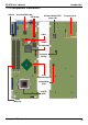
FS-979 User’s Manual Hardware Setup Chapter 2 2.
FS-979 User’s Manual Hardware Setup 2.2 2.2.
FS-979 User’s Manual Hardware Setup 2.
FS-979 User’s Manual Hardware Setup 2.4 2.4.1 FS-979 has a LGA755 CPU socket onboard; please check following steps to install the processor properly. Intel® Pentium 4 processor Package type: 775 pin PLGA L2 Cache: 1MB FSB: 800MHz (200MHz x 4) Manufacturing: 90nm Intel Hyper Threading Technology supported Check point 1. Lift this bar 3. Place the CPU on the top of 2. Uncover this plate 4. Lock this bar the pins 3.
FS-979 User’s Manual Hardware Setup 2.4.2 FS-979 has four 240-pin DDR2 DIMM support up to 4GB of memory capacity. The memory frequency supports 400/533MHz (100MHz x 4 or 133MHz x 4). Only Non-ECC memory is supported. Dual-Channel technology is supported while applying two same modules. Notice: When applying 4GB of memory, due to the memory resource issue, the available memory size would be less than 4GB.
FS-979 User’s Manual Hardware Setup 2.5 The board’s data of CMOS can be setting in BIOS. If the board refuses to boot due to inappropriate CMOS settings, here is how to proceed to clear (reset) the CMOS to its default values.
FS-979 User’s Manual Hardware Setup 2.6 The Intel® ICH6R (south bridge chip) supports one enhanced IDE interface, dual channel for two ATAPI devices with ATA100. Based on this function, FS-979 has one 40-pin IDE connector with jumper selectable for pin-20 +5V supported. The jumper JDOM is two-pin type for pin-20 supplied with +5V to apply the DOM (Disk on Module).
FS-979 User’s Manual Hardware Setup 2.7 FS-979 has four Serial ATA interfaces with RAID function, the transfer rate of the Serial ATA can be up to 150MB/s. Please go to http://www.serialata.org/ for more about Serial ATA technology information. Based on Intel® ICH6R, it supports Intel® Matrix Storage Technology with combination of RAID 0 and RAID 1 modes. The main features of RAID on ICH6R are listed below: 1. Supports for up to RAID volumes on a single, two-hard drive RAID array.
FS-979 User’s Manual Hardware Setup 2.8 The board comes with an Intel PRO/100 LAN with 82562EZ PHY, or up to three Intel PRO/1000 Gigabit LAN with 82570EI for PCI-Express 1x bus. The PCI-Express is the last expansion interface technology, for its serial data transfer scheme, each 1x lane will be up to 500MB/s (duplex).
FS-979 User’s Manual Hardware Setup 2.9
FS-979 User’s Manual Hardware Setup 2.10 FS-979 integrates with Intel® 915G GMCH for Intel Graphic Media Accelerator (GMA) 900 technology. It supports Intel® DVMT (Dynamic Video Memory Technology) 3.0 for up to 224MB frame buffer size shared with system memory. With a 333MHz core and DirectX 9 and OpenGL acceleration, FS-979 provides the powerful onboard graphics interface without additional graphic card.
FS-979 User’s Manual Hardware Setup Connector: CN_DVI Connector type: 26-pin header connector (pitch = 2.
FS-979 User’s Manual Hardware Setup 2.11 The board has one Compact Flash Type-II socket, users can apply embedded system on CF card or Micro drives, the jumper JCFSEL can let you select operating mode under master or slave. The Compact Flash socket supports storage type only.
FS-979 User’s Manual Hardware Setup 2.12 The board supports 4 USB2.0 ports based on Intel® ICH6R, which can support up to 480Mbps of transfer rate, and offer 500mA for maximum rating. The Intel® ICH6R contains and Enhanced Host Controller Interface (EHCI) and four Universal Host Controller Interfaces (UHCI), it can determine whether your connected device is for USB1.1 or USB2.0, and change the transfer rate automatically.
FS-979 User’s Manual Hardware Setup 2.13 The board comes with a 4-pin AT power connector and a 4-pin additional 12V power connector for powering the board, three fan connectors for Northbridge, CPU and system. The board also provides a 3-pin ATX function connector. You can just connect the two power connectors without any backplane to work. 2.13.
FS-979 User’s Manual Hardware Setup 2.13.
FS-979 User’s Manual Hardware Setup 2.14 The board supports one RS232 serial port and one jumper selectable RS232/422/485 serial ports. The jumper JCSEL1 & JCSEL2 can let you configure the communicating modes for COM2.
FS-979 User’s Manual Hardware Setup 2.15 The board provides a 12-pin General Purpose I/O interface, with programmable 8-bit I/O (4-bit input & 4-bit output). Connector: CN_DIO Type: onboard 2 x 6-pin header, pitch=2.
FS-979 User’s Manual Hardware Setup 2.16 The JFRNT provides front control panel of the board, such as power button, reset and beeper, etc. Please check well before you connecting the cables on the chassis. Connector: JFRNT Type: onboard 14-pin (2 x 7) 2.
FS-979 User’s Manual (This Page is Left for Blank) 32
FS-979 User’s Manual System Configuration Chapter 3 3.1 Based on Intel® ICH6R Southbridge chip, the board supports 4 Serial ATA ports; please follow the touring guide to setup your Serial ATA devices. For Windows 98/SE/ME, Windows NT4.0 and DOS system, they only support up to 4 IDE devices including SATA devices, and Windows 2000/XP/Server2003 have no such limitation.
FS-979 User’s Manual System Configuration SATA Mode: This option can let you select whether the Serial ATA hard drives would work under normal IDE mode or RAID mode. The RAID mode need more than one HDD is applied. Once you enable the RAID mode, the boot-up screen would pop up the RAID configuration option for setup.
FS-979 User’s Manual System Configuration On-Chip Serial ATA mode: This option can let you select operation modes of Serial ATA drives. Disabled: To disable the onboard Serial ATA controller. Auto: To allow the system select the optimized mode automatically. Combined mode: PATA and SATA work as two channels for supporting two drives on each channel. Enhanced mode: Max supported of the PATA and SATA for up to 6 drives. SATA Only: To disable the PATA and only apply the SATA drives.
FS-979 User’s Manual System Configuration 3.2 The board integrates Intel® ICH6R with RAID function for Serial ATA drives, and supports the configurations below: RAID 0 (Stripping): Two hard drives operating as one drive for optimized data R/W performance. It needs two unused drives to build this operation. RAID 1 (Mirroring): Copies the data from first drive to second drive for data security, and if one drive fails, the system would access the applications to the workable drive.
FS-979 User’s Manual System Configuration You can setup the RAID under operation system for Microsoft® Windows XP SP1 or Windows 2000 SP4 version, please install the Intel® Application Accelerator Ver.4.5 later to support RAID configuration with Intel® Matrix Storage Technology. 1. After installing Intel Application Accelerator, please execute Intel® Storage Utility. Demo configuration for 2 SATA Drives and set as Intel Matrix Storage Technology set 2.
FS-979 User’s Manual System Configuration 3. Please select two hard drives to prepare to set the RAID volume 4. Specify the Volume size Tune this bar to specify the volume size, if you specify the volume size lower than maximum, you can create a second volume for another RAID set. (Make RAID 0+1 on only two hard drives) 5. Repeat the step 1 to create second volume as RAID Level 1. For other configuration set please click Help on tool bar.
FS-979 User’s Manual System Configuration 3.3
FS-979 User’s Manual System Configuration Fixed + DVMT Memory Size: You can select the fixed amount and the DVMT amount at the same time for a guaranteed video memory and additional dynamic video memory, please check the table below for available setting.
FS-979 User’s Manual System Configuration 3.4 Based on Intel 915G GMCH with GMA 900 (Graphic Media Accelerator), the board supports two DACs for display device as different resolution and color bit. Please install the Intel Graphic Driver before you starting setup display devices. 1. Click right button on the desktop to lunch display properties You can find two DACs on this setup screen, to select each for resolution and color bit setup.
FS-979 User’s Manual System Configuration 3. This setup options can let you define each device settings.
FS-979 User’s Manual BIOS Setup Chapter 4 The motherboard uses the Award BIOS for the system configuration. The Award BIOS in the single board computer is a customized version of the industrial standard BIOS for IBM PC AT-compatible computers. It supports Intel x86 and compatible CPU architecture based processors and computers. The BIOS provides critical low-level support for the system central processing, memory and I/O sub-systems.
FS-979 User’s Manual (This Page is Left for Blank) 44
FS-979 User’s Manual I/O Port Pin Assignment Appendix A A.
FS-979 User’s Manual I/O Port Pin Assignment A.
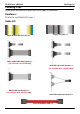
FS-979 User’s Manual I/O Port Pin Assignment A.5 < Parallel Port> Connector: CN_LPT Type: 26-pin (2 x 13) 2.54-pitch box header Pin 1 2 3 4 5 6 7 8 9 10 11 12 13 Description STROBED0 D1 D2 D3 D4 D5 D6 D7 ACKNOWLEDGEBUSY PAPER EMPTY SELECT+ Pin 14 15 16 17 18 19 20 21 22 23 24 25 26 2 26 1 25 Description AUTO FEEDERRORINITIALIZESELECT INPUTGround Ground Ground Ground Ground Ground Ground Ground N/C A.6 1 2 3 4 5 A.6.
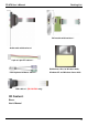
FS-979 User’s Manual I/O Port Pin Assignment 6 A.7 11 1 2 3 4 5 Connector: VGA Type: 15-pin D-sub female connector on bracket 12 13 14 15 10 Pin 1 2 3 4 5 Description RED GREEN BLUE N/C Ground Pin 6 7 8 9 10 Description Ground Ground Ground LVGA5V Ground Pin 11 12 13 14 15 Description N/C 5VCDA HSYNC VSYNC 5VCLK A.8 A.8.
FS-979 User’s Manual I/O Port Pin Assignment A.9 1 Connector: CN_ATKB Type: 5-pin box header 5 Pin Description 1 VCC 2 Ground 3 N/C 4 DATA 5 CLK A.10 1 Connector: PS2 Type: 6-pin Mini-DIN connector on bracket Pin Description 1 KBD 2 MSD 3 Ground 2 4 VCC 5 KBC 3 5 6 4 6 MSC Note: The PS/2 connector supports standard PS/2 keyboard directly or both PS/2 keyboard and mouse through the PS/2 Y-type cable.
FS-979 User’s Manual (This Page is Left for Blank) 50
FS-979 User’s Manual Flash BIOS Appendix B B.1 BIOS Auto Flash Tool The board is based on Award BIOS and can be updated easily by the BIOS auto flash tool. You can download the tool online at the address below: http://www.award.com File name of the tool is “awdflash.exe”, it’s the utility that can write the data into the BIOS flash ship and update the BIOS. B.2 Flash Method 1. Please make a bootable floppy disk. 2. Get the last .bin files you want to update and copy it into the disk. 3.
FS-979 User’s Manual Contact Information Contact Information Any advice or comment about our products and service, or anything we can help you please don’t hesitate to contact with us. We will do our best to support you for your products, projects and business Annso Technology Co., Ltd Address The south faces industry area of Xia Gang Fu Hai road, Chang'an Town,Dongguan City, Guangdong, China TEL +86-769-81666360 FAX +86-769-81666306 Website http://www.annso.com E-mail Rita@annso.com.