Intel® Desktop Board DX58SO2 Product Guide Order Number: G13826-001
Revision History Revision -001 Revision History First release of the Intel® Desktop Board DX58SO2 Product Guide Date November 2010 Disclaimer INFORMATION IN THIS DOCUMENT IS PROVIDED IN CONNECTION WITH INTEL® PRODUCTS. NO LICENSE, EXPRESS OR IMPLIED, BY ESTOPPEL OR OTHERWISE, TO ANY INTELLECTUAL PROPERTY RIGHTS IS GRANTED BY THIS DOCUMENT.
Preface This Product Guide gives information about board layout, component installation, BIOS update, and regulatory requirements for Intel® Desktop Board DX58SO2. Intended Audience The Product Guide is intended for technically qualified personnel. It is not intended for general audiences. Use Only for Intended Applications All Intel Desktop Boards are evaluated as Information Technology Equipment (I.T.E.
Intel Desktop Board DX58SO2 Product Guide Terminology The table below gives descriptions of some common terms used in the product guide.
Contents 1 Desktop Board Features Supported Operating Systems..............................................................................11 Desktop Board Components.................................................................................12 Processor..........................................................................................................14 Main Memory.....................................................................................................15 Intel® X58 Express Chipset...
Intel Desktop Board DX58SO2 Product Guide 2 Installing and Replacing Desktop Board Components Before You Begin ...............................................................................................31 Installation Precautions.......................................................................................32 Prevent Power Supply Overload ....................................................................32 Observe Safety and Regulatory Requirements.............................................
Contents 4 Configuring for RAID Configuring for RAID Using Intel® Matrix Storage Technology ...................................69 Configuring the BIOS ..................................................................................69 Creating Your RAID Set ...............................................................................69 Loading the Intel Matrix Storage Technology RAID Drivers and Software ............70 Setting Up a “RAID Ready” System ....................................................
Intel Desktop Board DX58SO2 Product Guide 16. 17. 18. 19. 20. 21. 22. 23. 24. 25. 26. 27. 28. 29. 30. 31. Example Configuration Using Six DIMMs ..........................................................40 Use DDR3 DIMMs .........................................................................................41 Installing a DIMM .........................................................................................42 Installing a PCI Express x16 Card ......................................................
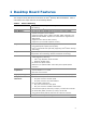
1 Desktop Board Features This chapter briefly describes the features of Intel® Desktop Board DX58SO2. Table 1 summarizes the major features of the Desktop Board. Table 1. Feature Summary Form Factor ATX (304.80 millimeters [12.00 inches] x 243.84 millimeters [9.
Intel Desktop Board DX58SO2 Product Guide Table 1.
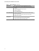
Desktop Board Features Supported Operating Systems • • • • • • • • • • • • • • • • • • • • Microsoft Microsoft Microsoft Microsoft Microsoft Microsoft Microsoft Microsoft Microsoft Microsoft Microsoft Microsoft Microsoft Microsoft Microsoft Microsoft Microsoft Microsoft Microsoft Microsoft Windows* 7 Ultimate 64-bit edition Windows 7 Ultimate 32-bit edition Windows 7 Professional 64-bit edition Windows 7 Professional 32-bit edition Windows 7 Home Premium 64-bit edition Windows 7 Home Premium 32-bit editi
Intel Desktop Board DX58SO2 Product Guide Desktop Board Components Figure 1 shows the approximate location of the major components on Intel Desktop Board DX58SO2. Figure 1.
Desktop Board Features Table 2. Intel Desktop Board DX58SO2 Components Label Description A Front panel audio header B PCI Express 1.1 x1 connector C S/PDIF header D PCI Express 2.0 x16 connector (x8 electrical) E PCI bus connector F PCI Express 2.0 x16 connector G PCI Express 1.1 x1 connector H PCI Express 2.
Intel Desktop Board DX58SO2 Product Guide Online Support For more information on Intel Desktop Board DX58SO2 consult the following online resources: • Intel Desktop Board DX58SO2 http://www.intel.com/products/motherboard/index.ht m • Desktop Board Support http://www.intel.com/p/en_US/support?iid=hdr+supp ort • Available configurations for Intel Desktop Board DX58SO2 http://ark.intel.com • Supported processors http://processormatch.intel.com • Chipset information http://www.intel.
Desktop Board Features Main Memory NOTE To be fully compliant with all applicable Intel ® SDRAM memory specifications, the board should be populated with DIMMs that support the Serial Presence Detect (SPD) data structure. If your memory modules do not support SPD, you will see a notification to this effect on the screen at power up. The BIOS will attempt to configure the memory controller for normal operation.
Intel Desktop Board DX58SO2 Product Guide Intel® X58 Express Chipset The Intel X58 Express Chipset consists of the following devices: • • Intel X58 Express Chipset I/O Hub (IOH) Intel 82801IJR I/O Controller Hub (ICH10R) The IOH provides interfaces to the processor and the PCI Express bus. ICH10R is the centralized controller for the board’s I/O paths. Go to the following link for more information about the Intel X58 Express Chipset: http://developer.intel.com/products/chipsets/index.
Desktop Board Features LAN Subsystem The Dual Gigabit (10/100/1000 Mb/s) LAN subsystem includes: • • • • Intel ICH10R Intel 82567LF Gigabit Ethernet LAN Controller Intel 82574L Gigabit Ethernet LAN Controller Two RJ-45 LAN connectors with integrated status LEDs The subsystem features: • • • CSMA/CD protocol engine LAN connect interface between ICH10R and the Intel 82567LF Gigabit Ethernet LAN Controller PCI bus power management Go to the following link for information about LAN software and drivers: ht
Intel Desktop Board DX58SO2 Product Guide Table 3 describes the LED states when the board is powered up and the LAN subsystem is operating. Table 3.
Desktop Board Features For information on configuring your system for RAID using Intel® Matrix Storage Technology see Chapter 4. The board also provides two 3.0 Gb/s external SATA (eSATA) channels via back panel connectors.
Intel Desktop Board DX58SO2 Product Guide Security Passwords The BIOS includes security features that restrict whether the BIOS Setup program can be accessed and who can boot the computer. A supervisor password and a user password can be set for the BIOS Setup and for booting the computer, with the following restrictions: • • • The supervisor password gives unrestricted access to view and change all Setup options.
Desktop Board Features Hardware Management The hardware management features of Intel Desktop Board DX58SO2 enable the board to be compatible with the Wired for Management (WfM) specification.
Intel Desktop Board DX58SO2 Product Guide Software Support ACPI ACPI gives the operating system direct control over the power management and Plug and Play functions of a computer. The use of ACPI with the Desktop Board requires an operating system that provides full ACPI support. Hardware Support Power Connectors ATX12V-compliant power supplies can turn off the computer power through system control.
Desktop Board Features Instantly Available PC Technology CAUTIONS For Instantly Available PC technology, the 5 V standby line for the power supply must be capable of delivering adequate +5 V standby current. Failure to provide adequate standby current when using this feature can damage the power supply and/or effect ACPI S3 sleep state functionality.
Intel Desktop Board DX58SO2 Product Guide Figure 4. Location of the Standby Power Indicator For more information on standby current requirements for the Desktop Board, refer to the Technical Product Specification at http://www.intel.com/products/motherboard/index.htm 1 Wake from USB NOTE Wake from USB requires the use of a USB peripheral that supports Wake from USB and an operating system that supports Wake from USB. USB bus activity wakes the computer from an ACPI S3 state.
Desktop Board Features Wake from Consumer IR Consumer IR device activity wakes the computer from an ACPI S3, S4, or S5 state. Onboard System Control Switches The board contains the following lighted button switches that can be used to control board operation: • • • • Base Clock Frequency Increase Base Clock Frequency Decrease Power Reset Figure 5.
Intel Desktop Board DX58SO2 Product Guide Base Clock Frequency Increase Switch This button switch can be used to overclock the board by increasing the processor’s Base Clock (BCLK) frequency by 1 MHz each time the switch is pressed. If the button is held down for approximately 0.5 seconds, the BCLK frequency will continue to increase by 1-MHz steps approximately once every 0.1 second. The BCLK frequency is used to set the frequencies of all major functional parts of the system.
Desktop Board Features Diagnostic/Status LEDs The Desktop Board provides 11 LEDs that allow you to monitor the board’s progress through the BIOS POST along with other board activities and conditions (see Figure 6). Figure 6.
Intel Desktop Board DX58SO2 Product Guide Diagnostic LEDs At initial power on, the eight diagnostic LEDs are off. When the BIOS starts an activity such as memory initialization, the corresponding LED starts flashing. Once the activity has completed, the LED will remain on. Table 4 lists the LEDs and describes their function. Table 4.
Desktop Board Features CPU and VR Hot LEDs The following red LEDs (see Figure 6) indicate the status of the processor and the board’s voltage regulation circuitry: • • The CPU LED (Figure 6, I) indicates an elevated temperature on the processor that could affect performance. The VR LED (Figure 6, J) indicates an elevated temperature in the processor voltage regulator circuit that could affect performance.
Intel Desktop Board DX58SO2 Product Guide 30
2 Installing and Replacing Desktop Board Components This chapter tells you how to: • • • • • • • • • • • • • Install the I/O shield Install and remove the Desktop Board Install and remove a processor Install and remove memory Install and remove a PCI Express x16 card Connect the Serial ATA cables Connect to the internal headers and connectors Connect to the audio system Connect chassis fan and power supply cables Set the BIOS configuration jumper Clear passwords Replace the battery Install the WiFi/BlueToo
Intel Desktop Board DX58SO2 Product Guide Installation Precautions When you install and test the Intel Desktop Board, observe all warnings and cautions in the installation instructions.
Installing and Replacing Desktop Board Components Installing the I/O Shield The Desktop Board comes with an I/O shield. When installed in the chassis, the shield blocks radio frequency transmissions, protects internal components from dust and foreign objects, and promotes correct airflow within the chassis. Install the I/O shield before installing the Desktop Board in the chassis. Place the shield inside the chassis as shown in Figure 7. Press the shield into place so that it fits tightly and securely.
Intel Desktop Board DX58SO2 Product Guide Installing and Removing the Desktop Board CAUTION Only qualified technical personnel should perform this procedure. Disconnect the computer from its power source before performing the procedures described here. Failure to disconnect the power before you open the computer can result in personal injury or equipment damage. Refer to your chassis manual for instructions on installing and removing the Desktop Board.
Installing and Replacing Desktop Board Components Installing and Removing a Processor Instructions on how to install the processor on the Desktop Board are given below. Installing a Processor CAUTION Before installing or removing a processor, make sure the AC power has been removed by unplugging the power cord from the computer; the standby power LED should not be lit (see Figure 4 on page 24). Failure to do so could damage the processor and the board. To install a processor, follow these instructions: 1.
Intel Desktop Board DX58SO2 Product Guide 3. Lift the load plate as shown in Figure 10, A. Do not touch the socket contacts. Figure 10.
Installing and Replacing Desktop Board Components 4. Remove the processor from the protective processor cover. Hold the processor only at the edges, being careful not to touch the bottom of the processor (see Figure 11). Do not discard the protective processor cover. Always replace the processor cover if the processor is removed from the socket. Figure 11. Remove the Processor from the Protective Processor Cover 5. Hold the processor with your thumb and index finger oriented as shown in Figure 12.
Intel Desktop Board DX58SO2 Product Guide 7. Close the load plate (Figure 13, A, B). As the load plate is closed, the socket cover (Figure 13, C) will pop off as shown. After the load plate is closed, engage the socket lever (Figure 13, D) under the latch. Figure 13. Close the Load Plate 8. Pickup the socket cover (Figure 13, C) and remove it from the board. NOTE Do not discard the socket cover; save it for possible future use. Always replace the socket cover if you remove the processor from the socket.
Installing and Replacing Desktop Board Components Installing the Processor Fan Heat Sink Intel Desktop Board DX58SO2 has mounting holes for a processor fan heat sink. For instructions on how to attach the processor fan heat sink to the Desktop Board, refer to the boxed processor manual or boxed thermal solution manual. Connecting the Processor Fan Heat Sink Cable Connect the processor fan heat sink cable to the 4-pin processor fan header (see Figure 14).
Intel Desktop Board DX58SO2 Product Guide Removing the Processor For instructions on how to remove the processor fan heat sink and processor, refer to the processor installation manual. Installing and Removing Memory Intel Desktop board DX58SO2 has six 240-pin DDR3 DIMM sockets arranged in three channels (A, B, and C). Each channel has two sockets as shown in the following illustrations. Optimal memory performance can be achieved by installing matched DIMMS of equal speed and size in each channel.
Installing and Replacing Desktop Board Components Installing DIMMs To make sure you have the correct DIMM, place it on the illustration of the DDR3 DIMM in Figure 17. All the notches should match with the DDR3 DIMM. Figure 17.
Intel Desktop Board DX58SO2 Product Guide NOTE Using a DIMM with a voltage rating higher than 1.65 V may damage the processor. To install a DIMM, follow these steps: 1. Observe the precautions in "Before You Begin" on page 31. 2. Turn off all peripheral devices connected to the computer. Turn off the computer and disconnect the AC power cord. 3. Remove the computer’s cover and locate the DIMM sockets (see Figure 18). Figure 18. Installing a DIMM 4.
Installing and Replacing Desktop Board Components Removing DIMMs To remove a DIMM, follow these steps: 1. 2. 3. 4. 5. Observe the precautions in "Before You Begin" on page 31. Turn off all peripheral devices connected to the computer. Turn off the computer. Remove the AC power cord from the computer. Remove the computer’s cover. Gently spread the retaining clips at each end of the DIMM socket. The DIMM pops out of the socket. 6.
Intel Desktop Board DX58SO2 Product Guide Figure 19. Installing a PCI Express x16 Card Removing a PCI Express x16 Add-in Card Follow these instructions to remove a PCI Express x16 card from a connector: 1. Observe the precautions in "Before You Begin" on page 31. 2. Remove the screw (Figure 20, A) that secures the card’s metal bracket to the chassis back panel. 3. Push the card ejector lever down using the tip of a pencil or similar tool (Figure 20, B) in the notch.
Installing and Replacing Desktop Board Components Figure 20. Removing a PCI Express x16 Card Installing Linked PCI Express x16 Graphics Cards The Desktop Board supports the use of linked PCI Express x16 graphics cards with Nvidia* SLI* technology and ATI* CrossFireX* technology. When installing linked graphics cards in the PCI Express x16 connectors, refer to the card manufacturer’s instructions to determine correct card placement and interconnection.
Intel Desktop Board DX58SO2 Product Guide 3. Place the second card in the secondary PCI Express x16 connector (Figure 21, A) and press down on the card until it is completely seated in the connector and the card retention notch on the card snaps into place around the retention mechanism pin on the connector. 4. Secure the card’s metal bracket to the chassis back panel with a screw (Figure 21, B). 5. Connect the two cards together with the SLI bridge (Figure 21, C) as shown. 6.
Installing and Replacing Desktop Board Components Connecting the Serial ATA (SATA) Cables SATA cables support the Serial ATA protocol. Each cable can be used to connect one internal SATA drive to the Desktop Board. The blue connectors support SATA 6 Gb/s and lower transfer rates and the black connectors support SATA 3 Gb/s and lower transfer rates. For correct cable function: 1. Observe the precaution in “Before You Begin” on page 31. 2.
Intel Desktop Board DX58SO2 Product Guide Connecting to the Internal Headers Before connecting cables to any of the internal headers, observe the precautions in “Before You Begin” on page 31. Figure 23 shows the location of the internal headers on Intel Desktop Board DX58SO2. Figure 23.
Installing and Replacing Desktop Board Components Front Panel Audio Header Figure 23, A shows the location of the front panel audio header. Table 5 shows the pin assignments and signal names for the front panel audio header. Table 5.
Intel Desktop Board DX58SO2 Product Guide Consumer IR (CIR) Headers The Desktop Board has two CIR headers: the input or receiver header (Figure 23, F) and the output or emitter header (Figure 23, D). The receiver header consists of a filtered translated infrared input compliant with Microsoft CIR specifications and a “learning” infrared input. The learning input is a high-pass input which the computer can use to “learn” to speak the infrared communication language of other user remotes.
Installing and Replacing Desktop Board Components Chassis Intrusion Header Figure 23, E shows the location of the chassis intrusion header. This header can be connected to a mechanical switch on the chassis to detect if the chassis cover is removed. Table 10 shows the pin assignments and signal names for the chassis intrusion header. Table 10. Chassis Intrusion Header Signal Names Pin Description 1 Intruder 2 Ground USB 2.0 Headers Figure 23, G shows the location of the USB 2.0 headers.
Intel Desktop Board DX58SO2 Product Guide Alternate Front Panel Power LED Header Figure 23, H shows the location of the alternate front panel power LED header. Pins 1 and 3 of this header duplicate the signals on pins 2 and 4 of the front panel header. If your chassis has a three-pin power LED cable, connect it to this header. Table 12 shows the pin assignments and signal names for the alternate front panel power LED header. Table 12.
Installing and Replacing Desktop Board Components Connecting to the Audio System After installing the RealTek audio driver from the Intel® Express Installer DVD-ROM, the multi-channel audio feature can be enabled. Figure 24 shows the back panel audio connectors. The default connector assignments are shown in the table.
Intel Desktop Board DX58SO2 Product Guide Connecting Chassis Fan and Power Supply Cables Connecting Chassis Fan Cables Connect chassis fan cables to the chassis fan headers on the Desktop Board. Figure 25 shows the location of the chassis fan headers. Figure 25.
Installing and Replacing Desktop Board Components Connecting Power Supply Cables Figure 26 shows the location of the power connectors. CAUTION Failure to use an appropriate power supply and/or not connecting the 12 V (Figure 26, A) power connector to the Desktop Board may result in damage to the board or the system may not function properly. The 2 x 12 pin main power connector (Figure 26, B) is backwards compatible with ATX12V power supplies with 2 x 10 connectors. Figure 26.
Intel Desktop Board DX58SO2 Product Guide Setting the BIOS Configuration Jumper NOTE Always turn off the power to the computer before moving the jumper. Moving the jumper with the power on may result in unreliable computer operation. Figure 27 shows the location of the Desktop Board’s BIOS configuration jumper block. Figure 27. Location of the BIOS Configuration Jumper Block The three-pin BIOS jumper block enables all board configurations to be done in the BIOS Setup program.
Installing and Replacing Desktop Board Components Table 14. Jumper Settings for the BIOS Setup Program Modes Jumper Setting Mode Description Normal (default) (1-2) The BIOS uses the current configuration and passwords for booting. Configure (2-3) After the Power-On Self-Test (POST) runs, the BIOS displays the Maintenance Menu. Use this menu to clear passwords. Recovery (None) The BIOS recovers data in the event of a failed BIOS update.
Intel Desktop Board DX58SO2 Product Guide 12. To restore normal operation, place the jumper on pins 1-2 as shown below. 13. Replace the cover, plug in the computer, and turn on the computer. Replacing the Battery A coin-cell battery (CR2032) powers the real-time clock and CMOS memory. When the computer is not plugged into a wall socket, the battery has an estimated life of three years. When the computer is plugged in, the standby current from the power supply extends the life of the battery.
Installing and Replacing Desktop Board Components VARO Räjähdysvaara, jos pariston tyyppi on väärä. Paristot on kierrätettävä, jos se on mahdollista. Käytetyt paristot on hävitettävä paikallisten ympäristömääräysten mukaisesti. VORSICHT Bei falschem Einsetzen einer neuen Batterie besteht Explosionsgefahr. Die Batterie darf nur durch denselben oder einen entsprechenden, vom Hersteller empfohlenen Batterietyp ersetzt werden. Entsorgen Sie verbrauchte Batterien den Anweisungen des Herstellers entsprechend.
Intel Desktop Board DX58SO2 Product Guide Προσοχή Υπάρχει κίνδυνος για έκρηξη σε περίπτωση που η μπαταρία αντικατασταθεί από μία λανθασμένου τύπου. Οι μπαταρίες θα πρέπει να ανακυκλώνονται όταν κάτι τέτοιο είναι δυνατό. Η απόρριψη των χρησιμοποιημένων μπαταριών πρέπει να γίνεται σύμφωνα με τους κατά τόπο περιβαλλοντικούς κανονισμούς. VIGYÁZAT Ha a telepet nem a megfelelő típusú telepre cseréli, az felrobbanhat. A telepeket lehetőség szerint újra kell hasznosítani.
Installing and Replacing Desktop Board Components POZOR Zamenjava baterije z baterijo drugačnega tipa lahko povzroči eksplozijo. Če je mogoče, baterije reciklirajte. Rabljene baterije zavrzite v skladu z lokalnimi okoljevarstvenimi predpisi. . UYARI Yanlış türde pil takıldığında patlama riski vardır. Piller mümkün olduğunda geri dönüştürülmelidir. Kullanılmış piller, yerel çevre yasalarına uygun olarak atılmalıdır. OСТОРОГА Використовуйте батареї правильного типу, інакше існуватиме ризик вибуху.
Intel Desktop Board DX58SO2 Product Guide To replace the battery, follow these steps: 1. Observe the precautions in "Before You Begin" (see page 31). 2. Turn off all peripheral devices connected to the computer. Disconnect the computer’s power cord from the AC power source (wall outlet or power adapter). 3. Remove the computer cover. 4. Locate the battery on the board (see Figure 28). 5. With a medium flat-bladed screwdriver, gently pry the battery free from its connector.
Installing and Replacing Desktop Board Components Installing the WiFi/Bluetooth* Module in a Desktop Chassis NOTE The WiFi/Bluetooth*module is supplemental hardware that is included with certain Desktop Boards. Additional WiFi/Bluetooth modules can be ordered online from http://click.intel.com/Desktop_system_parts-0-C97.aspx. Installing the WiFi/Bluetooth module that is shipped with Intel Desktop Board DX58SO2 in your desktop system allows you to connect to wireless networks and Bluetooth peripherals.
Intel Desktop Board DX58SO2 Product Guide Figure 29.
3 Updating the BIOS The BIOS Setup program can be used to view and change the BIOS settings for the computer. You can access the BIOS Setup program by pressing the key after the Power-On Self-Test (POST) memory test begins and before the operating system boot begins. This chapter tells you how to update the BIOS by either using the Intel Express BIOS Update utility or the Iflash Memory Update utility, and how to recover the BIOS if an update fails.
Intel Desktop Board DX58SO2 Product Guide Updating the BIOS Using the F7 Function Key To use this BIOS update method: 1. 2. 3. 4. 5. Download and save the Recovery BIOS (.BIO) file to a temporary directory. Copy the .BIO to a USB thumb drive. Plug the thumb drive into a USB port of the target computer. Shut down the target computer. Enable the F7 prompt display: a. Power the computer on. b. Enter the BIOS Setup by pressing F2 during boot. c. Go to the Advanced > Boot Configuration menu. d.
Updating the BIOS You can obtain either of these files through your computer supplier or by navigating to the Intel Desktop Board DX58SO2 page on the Intel World Wide Web site Download Center at http://downloadcenter.intel.com. On the DX58SO2 page, click on the “BIOS Update” link and then select the the Iflash BIOS Update file.
Intel Desktop Board DX58SO2 Product Guide CAUTION Do not interrupt the process or the system may not function properly. Follow these instructions to upgrade the BIOS using the ISO Image BIOS file: 1. Download the ISO Image BIOS file. 2. Using software capable of uncompressing and writing an ISO image file to CD, burn the data to a blank CD. NOTE Copying the ISO Image BIOS file to CD will not work. The completed CD should contain multiple files and a directory. 3.
4 Configuring for RAID Configuring for RAID Using Intel® Matrix Storage Technology NOTE Intel Matrix Storage Technology requires a Microsoft Windows 7, Microsoft Windows Vista, or Microsoft Windows XP operating system and SATA hard drives. Configuring the BIOS 1. Assemble your system and attach two or more SATA hard drives to the SATA connectors. 2. Enter system BIOS Setup by pressing after the Power-On-Self-Test (POST) memory tests begin. 3.
Intel Desktop Board DX58SO2 Product Guide Loading the Intel Matrix Storage Technology RAID Drivers and Software 1. Begin Windows Setup by booting from the Windows installation CD. 2. At the beginning of Windows Setup, press to install a third-party SCSI or RAID driver. When prompted, insert the diskette that contains the Intel Matrix Storage Technology RAID Driver in a USB floppy disk drive. Refer to http://support.microsoft.com/kb/916196/en-us for information on supported USB floppy disk drives.
Configuring for RAID Configuring for External RAID Using Marvell* Storage Technology Configuring the BIOS 1. Assemble your system and attach two External SATA hard drives to the Desktop Board’s two back panel eSATA connectors. 2. Enter system BIOS Setup by pressing the key after the Power-On-Self-Test (POST) memory tests begin. 3. Go to Advanced Peripheral Configuration Secondary SATA Controller; ensure that RAID is selected. 4. Then save your settings by pressing . Creating Your RAID Set 1.
Intel Desktop Board DX58SO2 Product Guide 72
A Error Messages and Indicators Intel Desktop Board DX58SO2 reports POST errors in three ways: • • • By sounding a beep code and blinking the front panel power LED By displaying an error message on the monitor By displaying diagnostic progress codes (POST codes) BIOS Error Codes Whenever a recoverable error occurs during POST, the BIOS causes the board’s speaker to beep and the front panel power LED to blink an error message indicating the problem (see Table 15). Table 15.
Intel Desktop Board DX58SO2 Product Guide BIOS Error Messages When a recoverable error occurs during the POST, the BIOS displays an error message describing the problem. Table 17 gives an explanation of the BIOS error messages. Table 17. BIOS Error Messages 74 Error Message Explanation PROCESSOR_THERMAL_TRIP_ERROR Processor was previously shutdown due to a thermal event (overheating). CMOS_BATTERY_ERROR The firmware has detected that a CMOS battery failure occurred.
Error Messages and Indicators Port 80h POST Codes During the POST, the BIOS generates diagnostic progress codes (POST codes) to I/O port 80h. If the POST fails, execution stops and the last POST code generated is left at port 80h and displayed on the Desktop Board’s seven-segment LED display shown in Figure 30. This code is useful for determining the point where an error occurred during the POST. Figure 30.
Intel Desktop Board DX58SO2 Product Guide Table 18 lists the Port 80h POST codes in hexadecimal notation. Table 18.
Error Messages and Indicators POST Code Description CPU Initialization (PEI, DXE, SMM) 41-43 Begin to end CPU PEI init 44-46 Begin to end CPU SMM init/relocate bases 47-4C CPU DXE phase begin to end 4D-4F CPU DXE SMM phase begin to end I/O Buses 50-52 PCI enumeration, allocation, hot plug 58, 59 Resetting USB bus 5A, 5B Resetting SATA bus and all devices 5F Unrecoverable error, start with PIC Boot Device Selection (BDS) 60-6F BDS driver entry E4 Entered DXE phase E7 Waiting for user
Intel Desktop Board DX58SO2 Product Guide 78
B Regulatory Compliance This appendix contains the following regulatory compliance information for Intel Desktop Board DX58SO2: • • • • • Safety standards European Union Declaration of Conformity statement Product Ecology statements Electromagnetic Compatibility (EMC) regulations Product certifications Safety Standards Intel Desktop Board DX58SO2 complies with the safety standards stated in Table 19 when correctly installed in a compatible host system. Table 19.
Intel Desktop Board DX58SO2 Product Guide European Union Declaration of Conformity Statement We, Intel Corporation, declare under our sole responsibility that the product Intel® Desktop Board DX58SO2 is in conformity with all applicable essential requirements necessary for CE marking, following the provisions of the European Council Directives 2004/108/EC (EMC Directive), 2006/95/EC (Low Voltage Directive), and 2002/95/EC (ROHS Directive).
Regulatory Compliance Polski Niniejszy produkt jest zgodny z postanowieniami Dyrektyw Unii Europejskiej 2004/108/EC, 206/95/EC i 2002/95/EC. Portuguese Este produto cumpre com as normas da Diretiva Européia 2004/108/EC, 2006/95/EC & 2002/95/EC. Español Este producto cumple con las normas del Directivo Europeo 2004/108/EC, 2006/95/EC & 2002/95/EC. Slovensky Tento produkt je v súlade s ustanoveniami európskych direktív 2004/108/EC, 2006/95/EC a 2002/95/EC.
Intel Desktop Board DX58SO2 Product Guide Deutsch Als Teil von Intels Engagement für den Umweltschutz hat das Unternehmen das Intel Produkt-Recyclingprogramm implementiert, das Einzelhandelskunden von Intel Markenprodukten ermöglicht, gebrauchte Produkte an ausgewählte Standorte für ordnungsgemäßes Recycling zurückzugeben. Details zu diesem Programm, einschließlich der darin eingeschlossenen Produkte, verfügbaren Standorte, Versandanweisungen, Bedingungen usw., finden Sie auf der http://intel.
Regulatory Compliance Portuguese Como parte deste compromisso com o respeito ao ambiente, a Intel implementou o Programa de Reciclagem de Produtos para que os consumidores finais possam enviar produtos Intel usados para locais selecionados, onde esses produtos são reciclados de maneira adequada. Consulte o site http://intel.
Intel Desktop Board DX58SO2 Product Guide China RoHS Intel Desktop Board DX58SO2 is a China RoHS-compliant product. The China Ministry of Information Industry (MII) stipulates that a material Self Declaration Table (SDT) must be included in a product’s user documentation. The SDT for Intel Desktop Board DX58SO2 is shown in Figure 31. Figure 31.
Regulatory Compliance EMC Regulations Intel Desktop Board DX58SO2 complies with the EMC regulations stated in Table 20 when correctly installed in a compatible host system. Table 20. EMC Regulations Regulation Title FCC 47 CFR Part 15, Subpart B Title 47 of the Code of Federal Regulations, Part 15, Subpart B, Radio Frequency Devices. (USA) ICES-003 Interference-Causing Equipment Standard, Digital Apparatus.
Intel Desktop Board DX58SO2 Product Guide radio or television reception, which can be determined by turning the equipment off and on, the user is encouraged to try to correct the interference by one or more of the following measures: • • • • Reorient or relocate the receiving antenna. Increase the separation between the equipment and the receiver. Connect the equipment to an outlet on a circuit other than the one to which the receiver is connected.
Regulatory Compliance Korea Class B Statement Korea Class B Statement translation: This equipment is for home use, and has acquired electromagnetic conformity registration, so it can be used not only in residential areas, but also other areas. Ensure Electromagnetic Compatibility (EMC) Compliance Before computer integration, make sure that the power supply and other modules or peripherals, as applicable, have passed Class B EMC testing and are marked accordingly.
Intel Desktop Board DX58SO2 Product Guide Product Certifications Board-Level Certifications Intel Desktop Board DX58SO2 has the regulatory compliance marks shown in Table 21. Table 21. Regulatory Compliance Marks Description UL joint US/Canada Recognized Component mark. Includes adjacent UL file number for Intel Desktop Boards: E210882. Mark FCC Declaration of Conformity logo mark for Class B equipment. CE mark.
Regulatory Compliance Chassis- and Component-Level Certifications Ensure that the chassis and certain components; such as the power supply, peripheral drives, wiring, and cables; are components certified for the country or market where used. Agency certification marks on the product are proof of certification. Typical product certifications include: In Europe The CE mark indicates compliance with all applicable European requirements.
Intel Desktop Board DX58SO2 Product Guide 90