
Frozen Dessert Maker User Manual
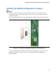
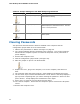
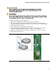

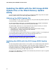
Table Of Contents
- Intel® Desktop Board DG35EC Product Guide
- Revision History
- Preface
- Contents
- 1 Desktop Board Features
- 2 Installing and Replacing Desktop Board Components
- Before You Begin
- Installation Precautions
- Installing the I/O Shield
- Installing and Removing the Desktop Board
- Installing and Removing a Processor
- Installing and Removing Memory
- Installing and Removing a PCI Express x16 Card
- Connecting the Diskette Drive Cable
- Connecting the IDE Cable
- Connecting Serial ATA (SATA) Cables
- Connecting to the Internal Headers and Connectors
- Connecting to the Onboard Audio System
- Connecting Chassis Fan and Power Supply Cables
- Setting the BIOS Configuration Jumper
- Clearing Passwords
- 3 Updating the BIOS
- A Error Messages and Indicators
- B Regulatory Compliance
Installing and Replacing Desktop Board Components
51
Setting the BIOS Configuration Jumper
NOTE
Always turn off the power and unplug the power cord from the computer before
moving the jumper. Moving the jumper with the power on may result in unreliable
computer operation.
Figure 27 shows the location of the Desktop Board’s BIOS confi
guration jumper block.
Figure 27. Location of the BIOS Configuration Jumper Block
The three-pin BIOS jumper block enables all board configurations to be done in the
BIOS Setup program. Table 13 shows the jumper setti
ngs for the BIOS Setup
program modes.