
Frozen Dessert Maker User Manual

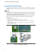
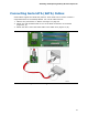
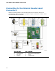
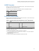
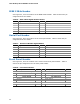
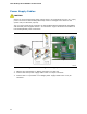
Table Of Contents
- Intel® Desktop Board DG35EC Product Guide
- Revision History
- Preface
- Contents
- 1 Desktop Board Features
- 2 Installing and Replacing Desktop Board Components
- Before You Begin
- Installation Precautions
- Installing the I/O Shield
- Installing and Removing the Desktop Board
- Installing and Removing a Processor
- Installing and Removing Memory
- Installing and Removing a PCI Express x16 Card
- Connecting the Diskette Drive Cable
- Connecting the IDE Cable
- Connecting Serial ATA (SATA) Cables
- Connecting to the Internal Headers and Connectors
- Connecting to the Onboard Audio System
- Connecting Chassis Fan and Power Supply Cables
- Setting the BIOS Configuration Jumper
- Clearing Passwords
- 3 Updating the BIOS
- A Error Messages and Indicators
- B Regulatory Compliance
Intel Desktop Board DG35EC Product Guide
46
IEEE 1394a Header
See Figure 23, C for the location of the IEEE 1394a header. Table 6 shows the pin
assignments for the header.
Table 6. IEEE 1394a Signal Header Names
Pin Signal Name Pin Signal Name
1 TPA1+ 2 TPA1-
3 Ground 4 Ground
5 TPA2+ 6 TPA2-
7 +12 V 8 +12 V
9 Key (no pin) 10 Ground
Serial Port Header
See Figure 23, D for the location of the serial port header. Table 7 shows the pin
assignments for the header.
Table 7. Serial Port Header Signal Names
Pin Signal Name Pin Signal Name
1 DCD 2 RXD#
3 TXD# 4 DTR
5 Ground 6 DSR
7 RTS 8 CTS
9 RI 10 No Connection
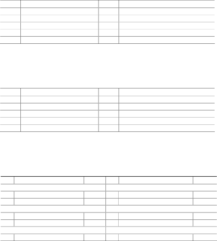
Front Panel Header
See Figure 23, E for the location of the multi-colored front panel header. Table 8
shows the pin assignments for the front panel header.
Table 8. Front Panel Header
Pin Description In/Out
Pin Description In/Out
Hard Drive Activity LED Power LED
1 Hard disk LED pull-up to +5 V
Out 2 Front panel green LED Out
3 Hard disk active LED Out 4 Front panel yellow LED Out
Reset Switch On/Off Switch
5 Ground 6 Power switch In
7 Reset switch In 8 Ground
Power Not Connected
9 Power Out 10 No pin