
Frozen Dessert Maker User Manual

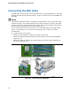
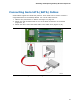
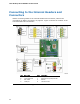
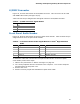
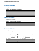
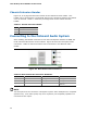
Table Of Contents
- Intel® Desktop Board DG35EC Product Guide
- Revision History
- Preface
- Contents
- 1 Desktop Board Features
- 2 Installing and Replacing Desktop Board Components
- Before You Begin
- Installation Precautions
- Installing the I/O Shield
- Installing and Removing the Desktop Board
- Installing and Removing a Processor
- Installing and Removing Memory
- Installing and Removing a PCI Express x16 Card
- Connecting the Diskette Drive Cable
- Connecting the IDE Cable
- Connecting Serial ATA (SATA) Cables
- Connecting to the Internal Headers and Connectors
- Connecting to the Onboard Audio System
- Connecting Chassis Fan and Power Supply Cables
- Setting the BIOS Configuration Jumper
- Clearing Passwords
- 3 Updating the BIOS
- A Error Messages and Indicators
- B Regulatory Compliance
Intel Desktop Board DG35EC Product Guide
44
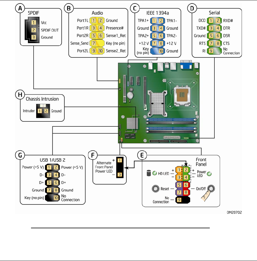
Connecting to the Internal Headers and
Connectors
Before connecting cables to the internal headers and connectors, observe the
precautions in “Before You Begin” on page 25. Figure 23 shows the location of the
internal headers and
connectors.
Item Description Item Description
A S/PDIF E
Front panel
B Front panel audio F
Alternate front panel power LED
C IEEE 1394a G
USB 2.0
D Serial port
H Chassis intrusion
Figure 23. Internal Headers