
Frozen Dessert Maker User Manual

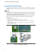
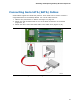
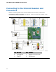
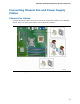
Table Of Contents
- Intel® Desktop Board DG35EC Product Guide
- Revision History
- Preface
- Contents
- 1 Desktop Board Features
- 2 Installing and Replacing Desktop Board Components
- Before You Begin
- Installation Precautions
- Installing the I/O Shield
- Installing and Removing the Desktop Board
- Installing and Removing a Processor
- Installing and Removing Memory
- Installing and Removing a PCI Express x16 Card
- Connecting the Diskette Drive Cable
- Connecting the IDE Cable
- Connecting Serial ATA (SATA) Cables
- Connecting to the Internal Headers and Connectors
- Connecting to the Onboard Audio System
- Connecting Chassis Fan and Power Supply Cables
- Setting the BIOS Configuration Jumper
- Clearing Passwords
- 3 Updating the BIOS
- A Error Messages and Indicators
- B Regulatory Compliance
Intel Desktop Board DG35EC Product Guide
42
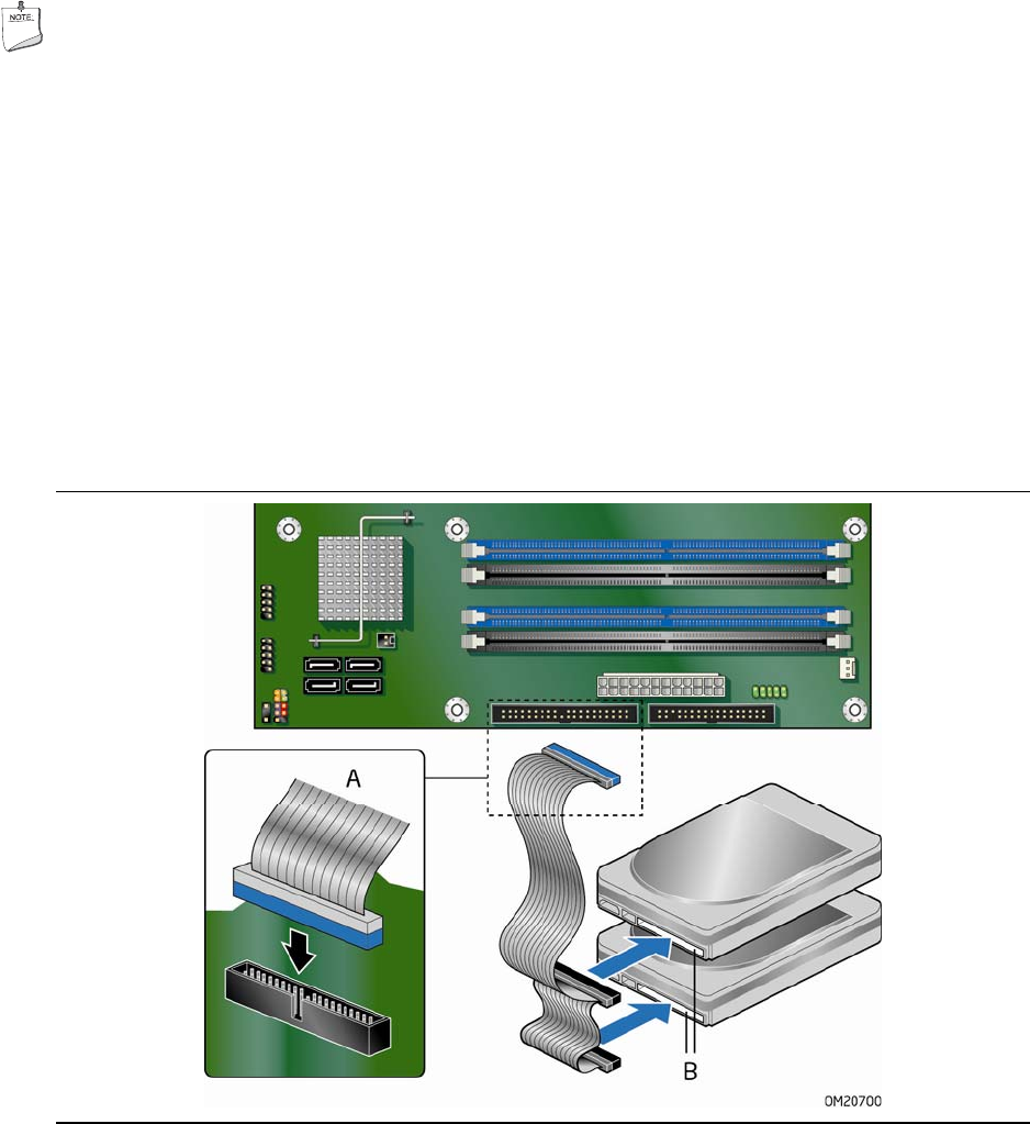
Connecting the IDE Cable
The IDE cable can be used to connect two IDE drives to the Desktop Board. The cable
supports the ATA-66/100 transfer protocol. Figure 21 shows the correct installation of
the cable.
NOTES
ATA-66/100 compatible cables are backward compatible with drives using slower IDE
transfer protocols. If an ATA-66/100 disk drive and a disk drive using any other IDE
transfer protocol are attached to the same cable, the maximum transfer rate between
the drives may be reduced to that of the slowest drive.
Do not connect an ATA device as a slave on the same IDE cable as an ATAPI master
device. For example, do not connect an ATA hard drive as a slave to an ATAPI
CD-ROM drive.
For correct function of the cable:
• Observe the precautions in "Before You Begin" on page 25.
• Attach the cable end with the single connect
or (blue) to the Intel Desktop Board
(Figure 21, A).
• Attach the cable end with the two cl
osely spaced connectors (gray and black) to
the drives (Figure 21, B).
Figure 21. Connecting the IDE Cable