
Frozen Dessert Maker User Manual
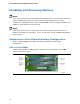
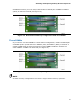
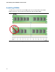
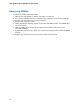
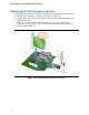
Table Of Contents
- Intel® Desktop Board DG35EC Product Guide
- Revision History
- Preface
- Contents
- 1 Desktop Board Features
- 2 Installing and Replacing Desktop Board Components
- Before You Begin
- Installation Precautions
- Installing the I/O Shield
- Installing and Removing the Desktop Board
- Installing and Removing a Processor
- Installing and Removing Memory
- Installing and Removing a PCI Express x16 Card
- Connecting the Diskette Drive Cable
- Connecting the IDE Cable
- Connecting Serial ATA (SATA) Cables
- Connecting to the Internal Headers and Connectors
- Connecting to the Onboard Audio System
- Connecting Chassis Fan and Power Supply Cables
- Setting the BIOS Configuration Jumper
- Clearing Passwords
- 3 Updating the BIOS
- A Error Messages and Indicators
- B Regulatory Compliance
Installing and Replacing Desktop Board Components
35
If additional memory is to be used, install another matched pair of DIMMs in DIMM 1
(black) in channels A and B (see Figure 14).
Figure 14. Dual Channel Memory Configuration with Four DIMMs
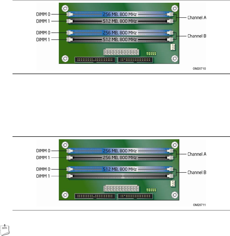
Three DIMMs
If you want to use three DIMMs in a dual-channel configuration, install a matched pair
of DIMMs equal in speed and size in DIMM 0 (blue) and DIMM 1 (black) of channel A.
Install a DIMM equal in speed and total size of the DIMMs installed in channel A in
either DIMM 0 or DIMM 1 of channel B (see Figure 15).
Figure 15. Dual Channel Memory Configuration with Three DIMMs
NOTE
All other memory configurations will result in single channel memory operation.