
Frozen Dessert Maker User Manual
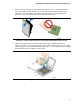
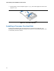
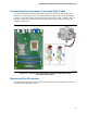
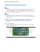
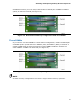
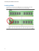
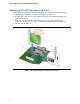
Table Of Contents
- Intel® Desktop Board DG35EC Product Guide
- Revision History
- Preface
- Contents
- 1 Desktop Board Features
- 2 Installing and Replacing Desktop Board Components
- Before You Begin
- Installation Precautions
- Installing the I/O Shield
- Installing and Removing the Desktop Board
- Installing and Removing a Processor
- Installing and Removing Memory
- Installing and Removing a PCI Express x16 Card
- Connecting the Diskette Drive Cable
- Connecting the IDE Cable
- Connecting Serial ATA (SATA) Cables
- Connecting to the Internal Headers and Connectors
- Connecting to the Onboard Audio System
- Connecting Chassis Fan and Power Supply Cables
- Setting the BIOS Configuration Jumper
- Clearing Passwords
- 3 Updating the BIOS
- A Error Messages and Indicators
- B Regulatory Compliance
Intel Desktop Board DG35EC Product Guide
34
Installing and Removing Memory
NOTE
To be fully compliant with all applicable Intel SDRAM memory specifications, the board
requires DIMMs that support the Serial Presence Detect (SPD) data structure.
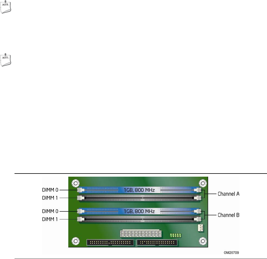
Desktop board DG35EC has four 240-pin DDR2 DIMM sockets arranged as DIMM 0 and
DIMM 1 in both Channel A and Channel B.
NOTE
Regardless of the memory configuration used (dual or single channel), Channel A,
DIMM 0 must always be populated. This is a requirement of the ICH9DH Manageability
Engine feature.
Guidelines for Dual Channel Memory Configuration
Before installing DIMMs, read and follow these guidelines for dual channel
configuration.
Two or Four DIMMs
Install a matched pair of DIMMs equal in speed and size (see Figure 13) in DIMM 0
(blue) of channels A and B.
Figure 13. Dual Channel Memory Configuration with Two DIMMs