
Frozen Dessert Maker User Manual
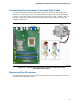
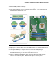
Table Of Contents
- Intel® Desktop Board DG35EC Product Guide
- Revision History
- Preface
- Contents
- 1 Desktop Board Features
- 2 Installing and Replacing Desktop Board Components
- Before You Begin
- Installation Precautions
- Installing the I/O Shield
- Installing and Removing the Desktop Board
- Installing and Removing a Processor
- Installing and Removing Memory
- Installing and Removing a PCI Express x16 Card
- Connecting the Diskette Drive Cable
- Connecting the IDE Cable
- Connecting Serial ATA (SATA) Cables
- Connecting to the Internal Headers and Connectors
- Connecting to the Onboard Audio System
- Connecting Chassis Fan and Power Supply Cables
- Setting the BIOS Configuration Jumper
- Clearing Passwords
- 3 Updating the BIOS
- A Error Messages and Indicators
- B Regulatory Compliance
Installing and Replacing Desktop Board Components
33
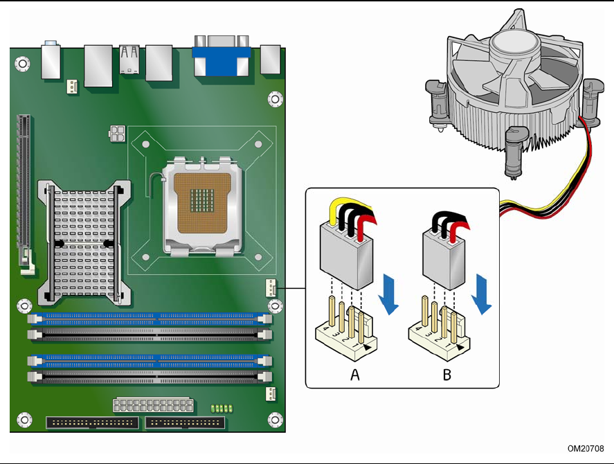
Connecting the Processor Fan Heat Sink Cable
Connect the processor fan heat sink cable to the 4-pin processor fan header (see
Figure 12). A fan with a 4-pi
n connector as shown in Figure 12, A is recommended;
however, a fan with a 3-pin connector (Figure 12, B) can be used. However, since a
fan
with a 3-pin connector cannot use the onboard fan control, the fan will always
operate at full speed.
Figure 12. Connecting the Processor Fan Heat Sink Cable to the
Processor Fan Header
Removing the Processor
For instructions on how to remove the processor fan heat sink and processor, refer to
the processor installation manual.