
Frozen Dessert Maker User Manual
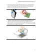
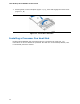
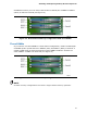
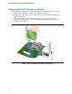
Table Of Contents
- Intel® Desktop Board DG35EC Product Guide
- Revision History
- Preface
- Contents
- 1 Desktop Board Features
- 2 Installing and Replacing Desktop Board Components
- Before You Begin
- Installation Precautions
- Installing the I/O Shield
- Installing and Removing the Desktop Board
- Installing and Removing a Processor
- Installing and Removing Memory
- Installing and Removing a PCI Express x16 Card
- Connecting the Diskette Drive Cable
- Connecting the IDE Cable
- Connecting Serial ATA (SATA) Cables
- Connecting to the Internal Headers and Connectors
- Connecting to the Onboard Audio System
- Connecting Chassis Fan and Power Supply Cables
- Setting the BIOS Configuration Jumper
- Clearing Passwords
- 3 Updating the BIOS
- A Error Messages and Indicators
- B Regulatory Compliance
Installing and Replacing Desktop Board Components
31
5. Remove the processor from the protective processor cover. Hold the processor
only at the edges, being careful not to touch the bottom of the processor (see
Figure 9). Do not discard the
protective processor cover. Always replace the
processor cover if the processor is removed from the socket.
Figure 9. Remove the Processor from the Protective Processor Cover
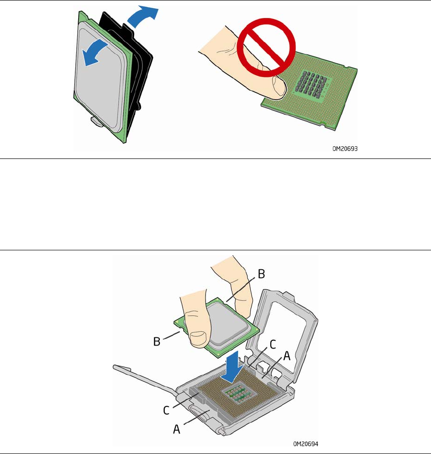
6. Hold the processor with your thumb and index fingers oriented as shown in
Figure 10. Make sure your fingers align to the socket cutouts (Figure 10, A). Align
notches
(Figure 10, B) with the socket (Figure 10, C). Lower the processor straight
dow
n without tilting or sliding it in the socket.
Figure 10. Install the Processor