
Frozen Dessert Maker User Manual
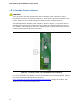

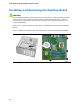
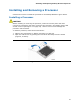
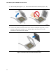
Table Of Contents
- Intel® Desktop Board DG35EC Product Guide
- Revision History
- Preface
- Contents
- 1 Desktop Board Features
- 2 Installing and Replacing Desktop Board Components
- Before You Begin
- Installation Precautions
- Installing the I/O Shield
- Installing and Removing the Desktop Board
- Installing and Removing a Processor
- Installing and Removing Memory
- Installing and Removing a PCI Express x16 Card
- Connecting the Diskette Drive Cable
- Connecting the IDE Cable
- Connecting Serial ATA (SATA) Cables
- Connecting to the Internal Headers and Connectors
- Connecting to the Onboard Audio System
- Connecting Chassis Fan and Power Supply Cables
- Setting the BIOS Configuration Jumper
- Clearing Passwords
- 3 Updating the BIOS
- A Error Messages and Indicators
- B Regulatory Compliance
Intel Desktop Board DG35EC Product Guide
30
3. Lift the load plate (Figure 7, A). Do not touch the socket contacts (Figure 7, B).
Figure 7. Lift the Load Plate
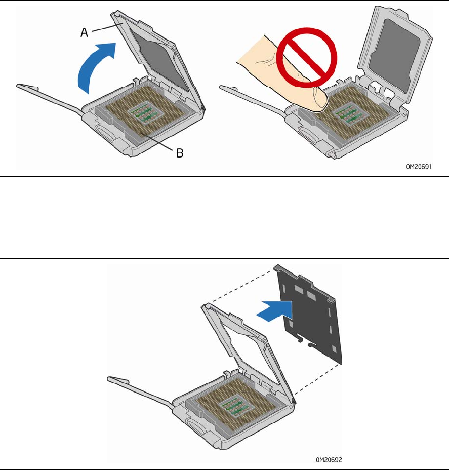
4. Remove the plastic protective socket cover from the load plate (Figure 8). Do not
discard the protective socket cover. Always replace the socket cover if the
processor is removed from the socket.
Figure 8. Remove the Protective Socket Cover