
Frozen Dessert Maker User Manual
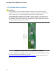

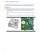
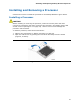
Table Of Contents
- Intel® Desktop Board DG35EC Product Guide
- Revision History
- Preface
- Contents
- 1 Desktop Board Features
- 2 Installing and Replacing Desktop Board Components
- Before You Begin
- Installation Precautions
- Installing the I/O Shield
- Installing and Removing the Desktop Board
- Installing and Removing a Processor
- Installing and Removing Memory
- Installing and Removing a PCI Express x16 Card
- Connecting the Diskette Drive Cable
- Connecting the IDE Cable
- Connecting Serial ATA (SATA) Cables
- Connecting to the Internal Headers and Connectors
- Connecting to the Onboard Audio System
- Connecting Chassis Fan and Power Supply Cables
- Setting the BIOS Configuration Jumper
- Clearing Passwords
- 3 Updating the BIOS
- A Error Messages and Indicators
- B Regulatory Compliance
Intel Desktop Board DG35EC Product Guide
28
Installing and Removing the Desktop Board
CAUTION
Only qualified technical personnel should do this procedure. Disconnect the computer
from its power source before performing the procedures described here. Failure to
disconnect the power before you open the computer can result in personal injury or
equipment damage.
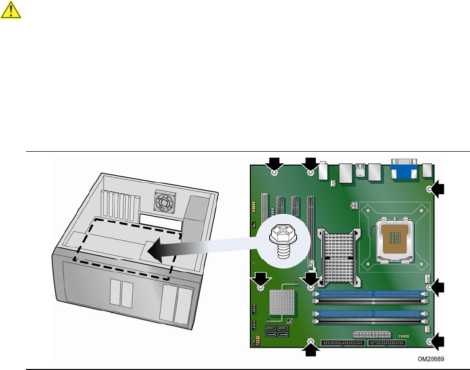
Refer to your chassis manual for instructions on installing and removing the Desktop
Board.
Figure 5 shows the location of t
he mounting screw holes for Desktop Board DG35EC.
Figure 5. Desktop Board DG35EC Mounting Screw Hole Locations