
Frozen Dessert Maker User Manual
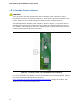

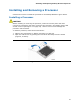
Table Of Contents
- Intel® Desktop Board DG35EC Product Guide
- Revision History
- Preface
- Contents
- 1 Desktop Board Features
- 2 Installing and Replacing Desktop Board Components
- Before You Begin
- Installation Precautions
- Installing the I/O Shield
- Installing and Removing the Desktop Board
- Installing and Removing a Processor
- Installing and Removing Memory
- Installing and Removing a PCI Express x16 Card
- Connecting the Diskette Drive Cable
- Connecting the IDE Cable
- Connecting Serial ATA (SATA) Cables
- Connecting to the Internal Headers and Connectors
- Connecting to the Onboard Audio System
- Connecting Chassis Fan and Power Supply Cables
- Setting the BIOS Configuration Jumper
- Clearing Passwords
- 3 Updating the BIOS
- A Error Messages and Indicators
- B Regulatory Compliance
Installing and Replacing Desktop Board Components
27
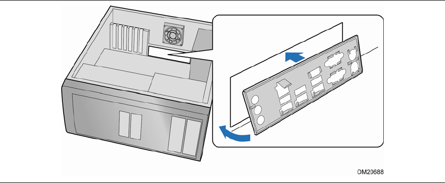
Installing the I/O Shield
The Desktop Board comes with an I/O shield. When installed in the chassis, the shield
blocks radio frequency transmissions, protects internal components from dust and
foreign objects, and promotes correct airflow within the chassis.
Install the I/O shield before installing the Desktop Board in the chassis. Place the
shield inside the chassis as shown in Figure 4. Press the shield into place so that it fits
t
ightly and securely. If the shield does not fit, obtain a properly sized shield from the
chassis supplier.
Figure 4. Installing the I/O Shield