
Frozen Dessert Maker User Manual
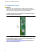

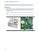
Table Of Contents
- Intel® Desktop Board DG35EC Product Guide
- Revision History
- Preface
- Contents
- 1 Desktop Board Features
- 2 Installing and Replacing Desktop Board Components
- Before You Begin
- Installation Precautions
- Installing the I/O Shield
- Installing and Removing the Desktop Board
- Installing and Removing a Processor
- Installing and Removing Memory
- Installing and Removing a PCI Express x16 Card
- Connecting the Diskette Drive Cable
- Connecting the IDE Cable
- Connecting Serial ATA (SATA) Cables
- Connecting to the Internal Headers and Connectors
- Connecting to the Onboard Audio System
- Connecting Chassis Fan and Power Supply Cables
- Setting the BIOS Configuration Jumper
- Clearing Passwords
- 3 Updating the BIOS
- A Error Messages and Indicators
- B Regulatory Compliance
Intel Desktop Board DG35EC Product Guide
22
+5 V Standby Power Indicator
CAUTION
If the AC power has been switched off and the standby power indicator is still lit,
disconnect the power cord before installing or removing any devices connected to the
board. Failure to do so could damage the board and any attached devices.
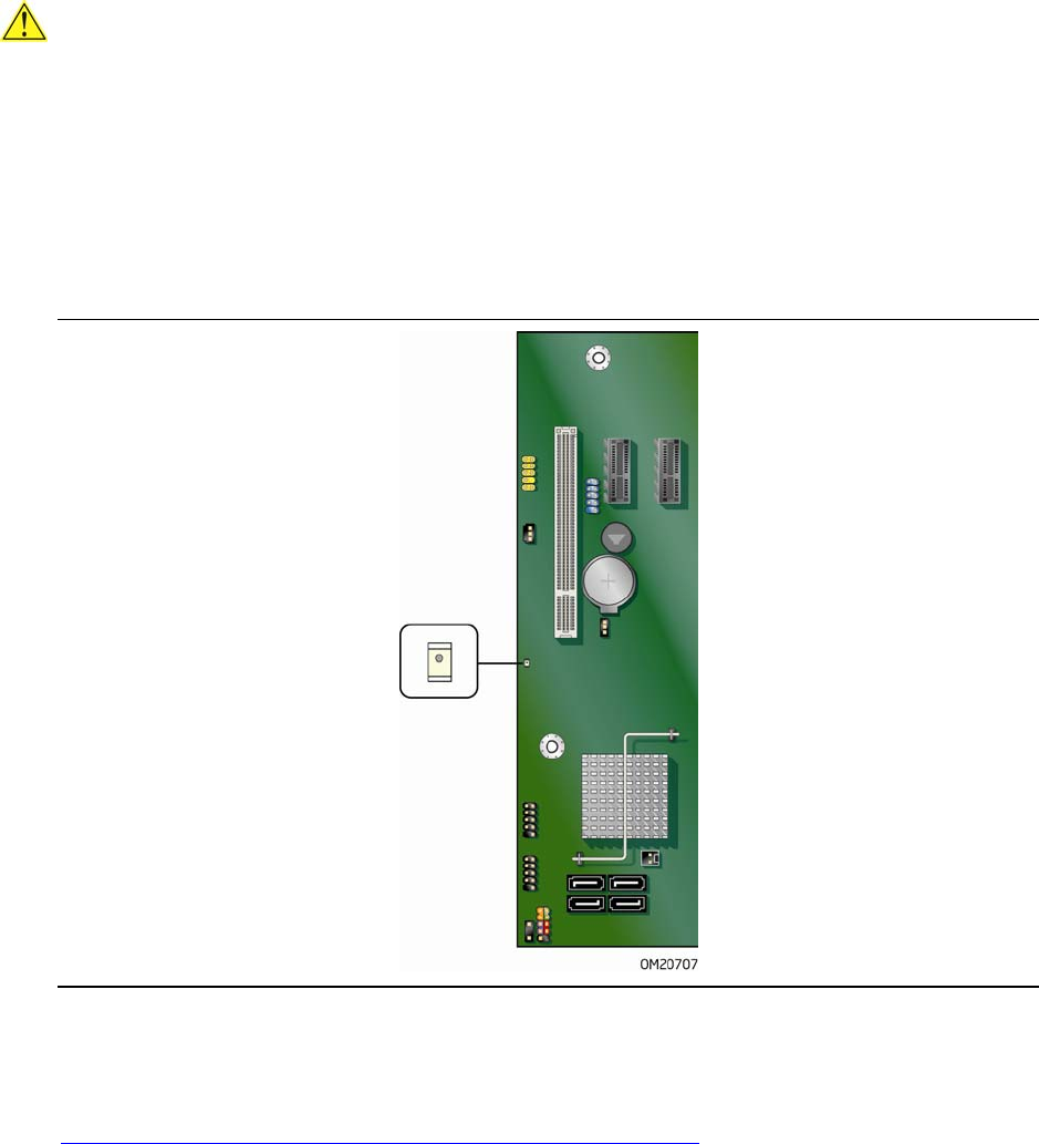
The Desktop Board’s standby power indicator, shown in Figure 3, is lit when there is
standby power still present on the board even when the computer appears to be off.
For example, when this green LED is lit, standby power is still present at the memory
module sockets and the PCI bus connectors.
Figure 3. Location of the +5 V Standby Power Indicator
For more information on standby current requirements for the Desktop Board, refer to
the Technical Product Specification by going to
http://support.intel.com/support/motherboards/desktop/
, finding the product, and
clicking on the Technical Documents tab.