Intel® CoreTM 2 Duo processor and Mobile Intel® GME965 Express Chipset Development Kit User Manual June 2007 Document Number: 316704-001
INFORMATION IN THIS DOCUMENT IS PROVIDED IN CONNECTION WITH INTEL® PRODUCTS. NO LICENSE, EXPRESS OR IMPLIED, BY ESTOPPEL OR OTHERWISE, TO ANY INTELLECTUAL PROPERTY RIGHTS IS GRANTED BY THIS DOCUMENT.
Contents 1 About This Manual ............................................................................................6 1.1 1.2 1.3 1.4 1.5 1.6 2 Getting Started............................................................................................... 15 2.1 2.2 2.3 2.4 2.5 2.6 3 3.5 3.6 3.7 Block Diagram ..................................................................................... 24 Mechanical Form Factor.........................................................................
Figures Figure Figure Figure Figure Figure Figure Figure Figure Figure Figure Figure Figure Figure Figure Figure 1. Development Board Block Diagram....................................................... 24 2. Development Board Component Locations ............................................. 39 3. Back Panel Connector Locations ........................................................... 42 4. D-Connector to Component Video Cable ................................................ 43 5.
Revision History Document Number Revision Number 316704 001 Description Initial public release.
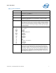
About This Manual 1 About This Manual This user’s manual describes the use of the Intel® CoreTM 2 Duo processor and Mobile Intel® GME965 Express Chipset development kit. This manual has been written for OEMs, system evaluators, and embedded system developers. This document defines all jumpers, headers, LED functions, and their locations on the development board, along with subsystem features and POST codes.
About This Manual Table 1. Text Conventions Notation Definition # The pound symbol (#) appended to a signal name indicates that the signal is active low. (e.g., PRSNT1#) Variables Variables are shown in italics. Variables must be replaced with correct values. Instructions Instruction mnemonics are shown in uppercase. When you are programming, instructions are not case-sensitive. You may use either uppercase or lowercase.
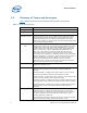
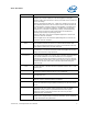
About This Manual 1.3 Glossary of Terms and Acronyms Table 2 defines conventions and terminology used throughout this document. Table 2. Terms and Acronyms Term/Acronym Definition Aggressor A network that transmits a coupled signal to another network. Anti-etch Any plane-split, void or cutout in a VCC or GND plane. Assisted Gunning Transceiver Logic+ The front-side bus uses a bus technology called AGTL+, or Assisted Gunning Transceiver Logic.
About This Manual Term/Acronym Definition manufacturer’s conditions required for AC timing specifications; i.e., ringback, etc.) and the output pin of the driving agent crossing the switching voltage when the driver is driving a test load used to specify the driver’s AC timings. Maximum and Minimum Flight Time - Flight time variations are caused by many different parameters.
About This Manual Term/Acronym System Bus Setup Window Simultaneous Switching Output Definition The System Bus is the microprocessor bus of the processor. The time between the beginning of Setup to Clock (TSU_MIN) and the arrival of a valid clock edge. This window may be different for each type of bus agent in the system.
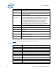
About This Manual Acronym Definition BIOS Basic Input/Output System CK-SSCD Spread Spectrum Differential Clock CMC Common Mode Choke CMOS Complementary Metal-Oxide-Semiconductor CPU Central Processing Unit (processor) DDR Double Data Rate DMI Direct Memory Interface ECC Error Correcting Code EEPROM Electrically Erasable Programmable Read-Only Memory EHCI Enhanced Host Controller Interface EMA Extended Media Access EMI Electro Magnetic Interference ESD Electrostatic Discharge EV
About This Manual Acronym 12 Definition LOM LAN on Motherboard LPC Low Pin Count LS Low-speed.
About This Manual Acronym Definition VREG Voltage Regulator XDP eXtended Debug Port 1.4 Support Options 1.4.1 Electronic Support Systems Intel’s web site (http://www.intel.com/) provides up-to-date technical information and product support. This information is available 24 hours per day, 7 days per week, providing technical information whenever you need it. 1.4.
About This Manual Intel Literature Fulfilment Center P.O. Box 5937 Denver, Colorado 80217-9808 USA Email a request to: intelsupport@hibbertgroup.com Please make sure to include in your mailed/emailed request: SKU # Company Name Your Name (first, last) Full mailing address Daytime Phone Number in case of questions Note: Please be aware not all documents are available in all media types. Some may only be available as a download. 1.
Getting Started 2 Getting Started This chapter identifies the development kit’s key components, features and specifications. It also details basic development board setup and operation. 2.1 Overview The development board consists of a baseboard populated with the Intel® CoreTM 2 Duo processor, the Mobile Intel® GME965 Express Chipset, other system board components and peripheral connectors.
Getting Started Development Board Implementation F E Comments Three x1 connectors Revision 1.1 compliant One x16 connector There are Five x1 PCI Express* slots but slots 2 and 4 are not intended for use with PCI Express* add-in cards. Only slots 1, 3 and 5 are supported. On-Board LAN 10/100/1000 Mbps connectivity from the Intel® 82566MM Gigabit Platform LAN Connect component The 82566MM is connected to the ICH via the ICH’s GLCI and LCI interfaces.
Getting Started Development Board Implementation ACPI Compliant Comments S0 – Power On S3 – Suspend to RAM S4 – Suspend to Disk Power Management S5 – Soft Off M0 – All Wells powered M1 – Main Well down. Only ME power on M-off – ME powered off Form Factor ATX 2.2 like form factor 10 layer board – 12” x 10.2” Note: Review the document provided with the Development Kit titled “Important Safety and Regulatory Information”.
Getting Started Note: While every care was taken to ensure the latest versions of drivers were provided on the enclosed CD at time of publication, newer revisions may be available. Updated drivers for Intel components can be found at: http://developer.intel.com/design/intarch/software/index.htm For all third-party components, please contact the appropriate vendor for updated drivers. Note: Software in the kit is provided free by the vendor and is only licensed for evaluation purposes.
Getting Started VGA Monitor: Any standard VGA or multi-resolution monitor may be used. The setup instructions in this chapter assume the use of a standard VGA monitor, TV, or flat panel monitor. Keyboard: The development board can support either a PS/2 or USB style keyboard. Mouse: The development board can support either a PS/2 or USB style mouse. Hard Drives and Optical Disc Drives: Up to Three SATA drives and two IDE devices (master and slave) may be connected to the development board.
Getting Started Other Devices and Adapters: The development board functions much like a standard desktop computer motherboard. Most PC-compatible peripherals can be attached and configured to work with the development board. 2.5 Setting Up the Development Board Once the necessary hardware (described in Section 2.4) has been gathered, follow the steps below to set up the development board. Note: To locate items discussed in the procedure below, please refer to Chapter 4. 1.
Getting Started Note: Ensure that the processor has been locked into the socket by turning the socket screw fully clockwise. Note: For proper installation of the CPU thermal solution, please refer to Appendix A 5. Connect a SATA or IDE hard disk drive. 6. Connect any additional storage devices to the development board. 7. Connect the keyboard and mouse. Connect a PS/2-style or USB mouse and keyboard (see Figure 3 on page 38 for connector locations).
Theory of Operation 3 Theory of Operation 3.1 Block Diagram Figure 1. Development Board Block Diagram 3.2 Mechanical Form Factor The development board conforms to the ATX form factor.
Theory of Operation chassis. Internal and rear panel system I/O connectors are described in Section 3.4. An overview of connector and slot locations is provided in Chapter 4. 3.3 Thermal Management The objective of thermal management is to ensure that the temperature of each component is maintained within specified functional limits. The functional temperature limit is the range within which the electrical circuits can be expected to meet their specified performance requirements.
Theory of Operation • SDVO interface via PCI Express* x16 connector provides maximum display flexibility o 3.4.1.1 Can drive up to two display outputs System Memory The development board supports DDR2 533/667 main memory. Two 200-pin SODIMM connectors (one per channel) on the development board support unbuffered, non-ECC, single and double-sided DDR2 533/667 MHz SODIMMs. These SODIMMs provide the ability to use up to 1 Gbit technology for a maximum of 4 GBytes system memory.
Theory of Operation 3.4.1.4 PCI Express x16 Slot The development board provides access to one x16 PCI Express* connector. Any industry standard x1 or x16 PCI Express* video adapter may be used with this interface. Additionally, any industry standard non-graphics x1, x4 or x8 adapter may also be used. x2 adapters are not part of the PCI Express* specification but x2 nongraphics devices are also supported.
Theory of Operation 3.4.2.3 On-Board LAN The development board has one RJ-45 interface – at connector J5A1 - through which 10/100/1000 ethernet is available. The ethernet MAC is located in the ICH8-M and the PHY is located externally in the 82566MM LAN Connect Interface (LCI) device. The 82566MM is connected to the ICH8-M via two interfaces: LCI for 10/100 Mbps traffic and GLCI (Gigabit LCI) for 1000Mbps traffic. Intel® Active Management Technology is optionally supported through these components.
Theory of Operation connector at J5A1. Four ports are routed to USB front panel headers at J6H3 and J6H4. The last is routed to the PCI-Express* docking connector at J9C1. There are Five UHCI Host Controllers and two EHCI Host Controllers. Each UHCI Host Controller includes a root hub with two separate USB ports each, for a total of ten legacy USB ports. The first EHCI Host Controller includes a root hub that supports up to six USB 2.
Theory of Operation Table 7. BIOS Location Strapping Options ICH8-M Signal GNT#0 SPI_CS1# BIOS Location 0 1 SPI 1 0 PCI 1 1 LPC (Default) Note: GNT#0 is configurable via jumper J8E2. Further details on its location can be found in Section 4.3. SPI_CS1# is configurable via stuffing option R7U12. By default R7U12 is not stuffed resulting in a SPI_CS1# strapping value of 1. 3.4.2.
Theory of Operation 3.4.3 POST Code Debugger A Port 80-83 Add-in card can be plugged into to the development board at the TPM header (J9A1). This card decodes the LPC bus BIOS POST codes and displays them on four 7-segment LED displays. For AMI* BIOS POST codes, please visit: http://www.ami.com 3.5 Clock Generation The development board uses a CK-505 and DB800 compatible solution. The FSB frequency is determined from decoding the processor BSEL[2:0] pin settings.
Theory of Operation State Description G0/S0/C3 Deep Sleep: DPSLP# signal active G0/S0/C4 Deeper Sleep: DPRSLP# signal active G1/S3 Suspend To RAM (all switched rails are turned off) G1/S4 Suspend To Disk G2/S5 Soft Off G3 Mechanical Off Table 10. Power Management M-States MState Description M0 Full on.
Theory of Operation Table 11. Sleep Signals and M-State Definition State Signal 3.
Theory of Operation Table 12. Development Board Voltage Rails 32 Component / Interface Voltage Plane Supply Rail Reference Designator CPU VR 5V +V5S +V5S_IMVP6 R1B1 CPU VR Battery +VBAT +VDC_PHASE R2P12 CPU VR Variable 6208_1_PHASE_LOUT +VCC_CORE R3D1 CPU VR Variable 6208_2_PHASE_LOUT +VCC_CORE R2D1 CPU VR Variable 6208_3_PHASE_LOUT +VCC_CORE R2D2 CPU 1.05V +V1.05S +V1.05S_CPU R3T2* and R3R7* CPU 1.5V +V1.5S +VCCA_PROC R3U1 (0.01Ω) GMCH VR Battery +VBATA 1.
Theory of Operation Component / Interface Voltage Plane Supply Rail Reference Designator GMCH 1.8V +V1.8 +V1.8_GMCH R5D1 GMCH 1.8V +V1.8_GMCH +V1.8_SM_CK R5D2 GMCH 1.8V +V1.8 +V1.8_TXLVDS R5U25 GMCH 1.8V +V1.8 +V1.8_DLVDS R5E5 GMCH 3.3V +V3.3S +V3.3S_HV R5U2 GMCH 3.3V +V3.3S +V3.3S_SYNC R5F9 GMCH 3.3V +VCCA_TVDAC +V3.3S_DAC_BG R5U19 (0.03Ω) GMCH 3.3V +V3.3S +V3.3S_PEG_BG R6E3 PCI-E Gfx 3.3V +V3.3S +V3.3S_PEG R6C1 PCI-E Gfx 3.3V +V3.3 +V3.
Theory of Operation 34 Component / Interface Voltage Plane Supply Rail Reference Designator Memory 1.8V +V1.8 +V1.8_DIMM1 R5B10 Memory 3.3V +V3.3M +V3.3M_DIMM0 R4C1 (0.022Ω) Memory 3.3V +V3.3M +V3.3M_DIMM1 R4B26 (0.022Ω) LAN 3.3V +V3.3M_LAN_SW +V3.3M_LAN R6A23 LAN 1.8V +V1.8_LAN +V1.8_LAN_M R6M1 LAN 1V +V1.0_LAN_M +V1.0_LAN_M_IN R6M3 PCI 3.3V +V3.3S +V3.3S_PCI R9D2 PCI 3.3V +V3.3 +V3.3_PCISLT3 R8C5* PCI 3.3V +V3.3S_PCI +V3.
Theory of Operation Component / Interface Voltage Plane Supply Rail Reference Designator Panel LVDS 5V +V5S +V3.3S_LVDS_DDC R6U9* CK505 3.3V +V3.3M_CK505 VDD_CK505 R5G11 CK505 3.3V +V3.3S +V3.3S_DB800 R7C10 CK505 0.9V IO_VOUT_D +VDDIO_CLK R5V11 LPC 3.3V +V3.3 +V3.3_LPCSLOT R8F2 LPC 5V +V5 +V5_LPCSLOT R8E2 TPM 5V +V5 V5_R1_TPM R9M7 TPM 3.3V +V3.3S V3.3S_R1_TPM R9M8 TPM 3.3V +V3.3A V3.3A_R1_TPM R9A8 SMC 3.3V +V3.3A +V3.
Theory of Operation Component / Interface Voltage Plane Supply Rail Reference Designator System ATX +V5A +V5_ATX R4J1* System ATX +V3.3A +V3.
Hardware Reference 4 Hardware Reference This section provides reference information on the hardware, including locations of development board components, connector pinout information and jumper settings. 4.1 Primary Features Figure 2 shows the major components of the development board and Table 13 gives a brief description of each component. Figure 2.
Hardware Reference Table 13.
Hardware Reference Reference Designator Function J7J4 PATA Connector J8A1 Reserved J8A2 Reserved J8B3 PCI Slot 3 J8B4 PCI Express Slot 3 J8D1 PCI Express Slot 4 J8E1 LPC Slot J8G2 Extended Mobile Access Header J8J1 SATA Port 0, Direct Connect J9A1 Trusted Platform Module Header J9C1 PCI Express Docking Interface J9E1 Scan Matrix Key Board Connector J9E2 HDA Header for MDC Interposer J9E3 LPC Hot Docking Connector J9E4 HDA Header for MDC Interposer J9G1 LPC Side Band Header
Hardware Reference Figure 3. Back Panel Connector Locations n o s p q r t u Table 14. Back Panel Connector Definitions 4.2.1 Item Description Ref Des Item Description Ref Des 1 PS/2 Mouse J1A1 5 RJ-45 LAN J5A1 2 TV-Out D-Connector J2A1 6 PS/2 Keyboard J1A1 3 Serial Port J2A2 7 VGA J2A2 4 3 USB Ports J3A1 8 2 USB Ports J5A1 TV-Out D-Connector The TV-Out D-connector supplies the necessary signals to support the Composite, SVideo, and Component TV standards.
Hardware Reference Figure 4. D-Connector to Component Video Cable Figure 5. D-Connector to Composite Video Cable Figure 6. D-Connector to S-Video Cable 4.3 Configuration Settings Note: Do not move jumpers with the power on. Always turn off the power and unplug the power cord from the computer before changing jumper settings. Failure to do so may cause damage to the development board. Figure 7 shows the location of the configuration jumpers and switches.
Hardware Reference The unsupported jumpers must remain in their default position or the operation of the development board is unpredictable. The development board is shipped with the jumpers and switches shunted in the default locations. Figure 7. Configuration Jumper and Switch Locations Table 15.
Hardware Reference Reference Designator Function Default Setting Override Optional Setting For each VID signal IN: Tied to logic low OUT: Tied to logic high 13 and 14 = VID0 11 and 12 = VID1 9 and 10 = VID2 7 and 8 = VID3 5 and 6 = VID4 3 and 4 = VID5 1 and 2 = VID6 J2F3 Reserved J2G1 GFX VID Code Override OUT Do not alter jumper setting OUT 1-2: Activate Override For each VID signal IN: Tied to logic low OUT: Tied to logic high 3 and 4 = VID0 5 and 6 = VID1 7 and 8 = VID2 9 and 10 = VID3 11 and
Hardware Reference 44 Reference Designator Function Default Setting J3J1 Reserved OUT Do not alter jumper setting J3J2 Reserved OUT Do not alter jumper setting J3J3 Reserved OUT Do not alter jumper setting J4H1 ME G3 to M1 J5H1 Reserved J5H2 Clear CMOS J6G1 Reserved OUT Do not alter jumper setting J6H2 Reserved IN Do not alter jumper setting J7D1 Super IO Reset J7J1 Reserved J7J2 SATA Power Enable OUT: Normal operation Optional Setting IN: Jump power state from G3 to M1 OU
Hardware Reference Reference Designator Function Default Setting Optional Setting H8 Programming NMI enabled programming J9H3 KBC Disable OUT: Normal operation, Keyboard Controller enabled IN: Keyboard Controller disabled J9H4 SMC MD0 IN: Normal operation.
Hardware Reference 4.5 LEDs The development board has a number of LEDs. These LEDs provide status for various functions on the development board. Figure 8 indicates the location of the LEDs and Table 16 describes their function. Figure 8. LED Locations Table 16.
Hardware Reference Function Reference Designator VID 0 CR1B1 VID 1 CR1B2 VID 2 CR1B3 VID 3 CR1B4 VID 4 CR1B5 VID 5 CR1B6 VID 6 CR1B7 M0/M1 CR4H1 System Power Good CR5J1 Reserved CR8G1 4.6 Other Headers, Slots and Sockets 4.6.1 H8 Programming Headers The microcontroller firmware for system management/keyboard/mouse control can be upgraded in two ways.
Hardware Reference d. J9H2 (1-2) (default: 1-X), disable 1 Hz Clock. 4. Attach an ATX power supply or AC to DC adapter to the system and power up the development board. 5. From the directory where you extracted the files, run the “kscflash ksc.bin / remote” command to program the H8 via the serial port. 6. Follow the instructions the flash utility provides. 7. With the development board powered off, return the jumpers to their default setting.
Hardware Reference Reference Designator 4.6.2.1 Slot/Socket Description Detail J6H5 Front Panel Header Table 28 J6H3, J6H4 USB Header Table 29 478 Pin Grid Array (Micro-FCPGA) Socket The pin locking mechanism on the CPU socket is released by rotating the screw on the socket 180 degrees counter-clockwise. CPU pins are keyed so as to only allow insertion in one orientation. DO NOT FORCE CPU into socket.
Hardware Reference Pin A11 Description PERST# Pin B11 Description WAKE# Key A12 GND B12 RSVD A13 REFCLK+ B13 GND A14 REFCLK- B14 LANE 0 (T+) A15 GND B15 LANE 0 (T-) A16 LANE 0 (R+) B16 GND A17 LANE 0 (R-) B17 PRSNT2* A18 GND B18 GND End of x1 Connector A19 RSVD B19 LANE 1 (T+) A20 GND B20 LANE 1 (T-) A21 LANE 1 (R+) B21 GND A22 LANE 1 (R-) B22 GND A23 GND B23 LANE 2 (T+) A24 GND B24 LANE 2 (T-) A25 LANE 2 (R+) B25 GND A26 LANE 2 (R-) B26 GND A
Hardware Reference Pin Description Pin Description A43 LANE 6 (R+) B43 GND A44 LANE 6 (R-) B44 GND A45 GND B45 LANE 7 (T+) A46 GND B46 LANE 7 (T-) A47 LANE 7 (R+) B47 GND A48 LANE 7 (R-) B48 PRSNT#2 A49 GND B49 GND End of x8 Connector A50 RSVD B50 LANE 8 (T+) A51 GND B51 LANE 8 (T-) A52 LANE 8 (R+) B52 GND A53 LANE 8 (R-) B53 GND A54 GND B54 LANE 9 (T+) A55 GND B55 LANE 9 (T-) A56 LANE 9 (R+) B56 GND A57 LANE 9 (R-) B57 GND A58 GND B58 LANE
Hardware Reference 4.6.2.3 Pin Description Pin Description A77 LANE 14 (R-) B77 GND A78 GND B78 LANE 15 (T+) A79 GND B79 LANE 15 (T-) A80 LANE 15 (R+) B80 GND A81 LANE 15 (R-) B81 PRST2# A82 GND B82 RSVD ADD2/Media Expansion Card (MEC) Slot When not being used for PCI Express*, the x16 slot can be used for Serial Digital Video Out (SDVO).
Hardware Reference Pin A18 Description GND Pin B18 Description GND End of x1 Connector A19 Reserved B19 SDVO_Green+ A20 GND B20 SDVO_Green- A21 SDVOB_Int+ B21 GND A22 SDVOB_Int- B22 GND A23 GND B23 SDVOB_Blue+ A24 GND B24 SDVOB_Blue- A25 SDVO_Stall+ B25 GND A26 SDVO_Stall- B26 GND A27 GND B27 SDVOB_Clk+ A28 GND B28 SDVOB_Clk- A29 N/C B29 GND A30 N/C B30 Reserved A31 GND B31 SDVO_CtrlData A32 Reserved B32 GND End of x4 Connector A33 Reserved B33
Hardware Reference Pin 54 Description Pin Description A50 Reserved B50 N/C A51 GND B51 N/C A52 N/C B52 GND A53 N/C B53 GND A54 GND B54 N/C A55 GND B55 N/C A56 N/C B56 GND A57 N/C B57 GND A58 GND B58 N/C A59 GND B59 N/C A60 N/C B60 GND A61 N/C B61 GND A62 GND B62 N/C A63 GND B63 N/C A64 N/C B64 GND A65 N/C B65 GND A66 GND B66 N/C A67 GND B67 N/C A68 N/C B68 GND A69 N/C B69 GND A70 GND B70 N/C A71 GND B71 N/C A72 N/
Hardware Reference Table 20. MEC Slot (J6B2) Pin Description Pin Description A1 N/C B1 12 V A2 12 V B2 12 V A3 12 V B3 Reserved A4 GND B4 GND A5 N/C B5 N/C A6 N/C B6 N/C A7 N/C B7 GND A8 N/C B8 3.3 V A9 3.3 V B9 N/C A10 3.3 V B10 +3.
Hardware Reference Pin Description Pin Description End of x4 Connector A33 Reserved B33 N/C A34 GND B34 N/C A35 N/C B35 GND A36 N/C B36 GND A37 GND B37 N/C A38 GND B38 N/C A39 N/C B39 GND A40 N/C B40 GND A41 GND B41 N/C A42 GND B42 N/C A43 N/C B43 GND A44 N/C B44 GND A45 GND B45 N/C A46 GND B46 N/C A47 N/C B47 GND A48 N/C B48 MEC_Enable A49 GND B49 GND End of x8 Connector 56 A50 Reserved B50 SDVOC_CLK+ A51 GND B51 SDVOC_CLK-
Hardware Reference Pin 4.6.2.
Hardware Reference Pin Description Pin Description Key 4.6.2.5 A12 GND B12 RSVD A13 REFCLK+ B13 GND A14 REFCLK- B14 LANE 0 (T+) A15 GND B15 LANE 0 (T-) A16 LANE 0 (R+) B16 GND A17 LANE 0 (R-) B17 PRSNT2* A18 GND B18 GND IDE Connector The IDE interface can support up to two devices, a master and a slave. Ensure that the jumpers on the devices are properly selected for the given configuration.
Hardware Reference 4.6.2.6 SATA Pinout Up to three SATA devices may be supported by the SATA connectors on the development board. Table 23 describes the SATA ‘Direct Connect’ connector and Table 24 describes the SATA ‘Cable Connect’ connectors. Table 23. SATA Port 0 ‘Direct Connect’ Connector Pinout (J8J1) Pin Signal 2 TX 3 TX# 5 RX# 6 RX 8, 9, 10 +3.3V 14, 15, 16 +5V 20, 21, 22 +12V 1, 4, 7, 11 GND 12, 13, 17, 19 GND Table 24.
Hardware Reference Connector J2B3 is used to power the CPU fan. Connectors J2C1 and J2F1 are not used in the default operation of the development board. Table 26. Fan Connectors (J2B3, J2C1) Pin Signal 1 +V 2 TACH 3 GND Table 27. Fan Connector (J2F1) Pin 4.6.2.8 Signal 1 +5V 2 NC 3 GND Front Panel Header (J6H5) The front panel header allows connection of the LEDs and switches typically found in an ATX chassis to the development board. Table 28.
Hardware Reference 16 4.6.2.9 +V5 5 volt supply USB Headers (J6H3, J6H4) The USB headers implement 4 additional USB ports on the development board. Connector J6H3 implements ports 7 and 8 and connector J6H4 implements ports 2 and 4. Table 29.
Hardware Reference Appendix A . Heatsink Installation Instructions It is necessary for the Intel® CoreTM 2 Duo processor to have a thermal solution attached to it in order to keep it within its operating temperature. Caution: An ESD wrist strap must be used when handling the board and installing the heatsink/fan assembly. A heatsink is included in the kit. To install the heatsink: 1. Remove the heatsink from its package and separate the fan heatsink portion from the heatsink backplate. Figure 9.
Hardware Reference Figure 10. Backplate Pins 4. Clean the die of the processor with isopropyl alcohol before the heatsink is attached to the processor. This ensures that the surface of the die is clean. 5. Remove the tube of thermal grease from the package and use it to coat the exposed die of the CPU with the thermal grease.
Hardware Reference Figure 11. Applying the Thermal Grease 6. Pick up the heatsink and squeeze the activation arm until it comes in contact with the base plate that is attached to the heatsink base. This will cause the springs on the heatsink attachment mechanism to compress. Figure 12.
Hardware Reference 7. While keeping the activation arm compressed, place the heatsink over the pins of the heatsink backplate. Lower the heatsink until the lugs have inserted into the base of the heatsink. Slide the heatsink over the lugs on the backplate pins so that the base is directly over the processor die and the pins on the backplate have travelled the entire length of the channel in the heatsink base.
Hardware Reference Figure 14. Plugging in the Fan Figure 15.