Desktop 3rd Generation Intel® Core™ Processor Family Specification Update September 2013 Revision 015 Reference Number: 326766
INFORMATION IN THIS DOCUMENT IS PROVIDED IN CONNECTION WITH INTEL PRODUCTS. NO LICENSE, EXPRESS OR IMPLIED, BY ESTOPPEL OR OTHERWISE, TO ANY INTELLECTUAL PROPERTY RIGHTS IS GRANTED BY THIS DOCUMENT.
Contents Contents Revision History ...............................................................................................................5 Preface ..............................................................................................................................6 Summary Tables of Changes ..........................................................................................8 Identification Information ..................................................................................
Contents 4 Specification Update
Revision History Revision Description Date 001 • Initial Release.
Preface This document is an update to the specifications contained in the Affected Documents table below. This document is a compilation of device and documentation errata, specification clarifications and changes. It is intended for hardware system manufacturers and software developers of applications, operating systems, or tools. Information types defined in Nomenclature are consolidated into the specification update and are no longer published in other documents.
Nomenclature Errata are design defects or errors. These may cause the processor behavior to deviate from published specifications. Hardware and software designed to be used with any given stepping must assume that all errata documented for that stepping are present on all devices. S-Spec Number is a five-digit code used to identify products. Products are differentiated by their unique characteristics such as, core speed, L2 cache size, package type, etc.
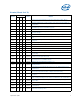
Summary Tables of Changes The following tables indicate the errata, specification changes, specification clarifications, or documentation changes which apply to the processor. Intel may fix some of the errata in a future stepping of the component, and account for the other outstanding issues through documentation or specification changes as noted. These tables uses the following notations: Codes Used in Summary Tables Stepping X: Errata exists in the stepping indicated.
Errata (Sheet 2 of 5) Steppings Number Status ERRATA E-1 L-1 N-0 BV7 X X X No Fix General Protection Fault (#GP) for Instructions Greater than 15 Bytes May be Preempted BV8 X X X No Fix LBR, BTS, BTM May Report a Wrong Address when an Exception/Interrupt Occurs in 64-bit Mode BV9 X X X No Fix Incorrect Address Computed For Last Byte of FXSAVE/FXRSTOR or XSAVE/ XRSTOR Image Leads to Partial Memory Update BV10 X X X No Fix Values for LBR/BTS/BTM Will be Incorrect after an Exit fro
Errata (Sheet 3 of 5) Steppings Number Status ERRATA E-1 L-1 N-0 BV33 X X X No Fix Clock Modulation Duty Cycle Cannot be Programmed to 6.
Errata (Sheet 4 of 5) Steppings Number Status ERRATA E-1 L-1 N-0 BV60 X X X No Fix The Processor May Not Comply With PCIe* Equalization Preset Reflection Requirements for 8 GT/s Mode of Operation BV61 X X X No Fix Processor May Issue PCIe* EIEOS at Incorrect Rate BV62 X X X No Fix Reduced Swing Output Mode Needs Zero De-emphasis to be Supported in PCIe* 5GT/s Speed BV63 X X X No Fix PCIe* Root-port Initiated Compliance State Transmitter Equalization Settings May be Incorrect BV
Errata (Sheet 5 of 5) Steppings Number Status ERRATA E-1 L-1 N-0 BV90 X X X No Fix During Package Power States Repeated PCIe* and/or DMI L1 Transitions May Cause a System BV91 X X X No Fix Instruction Fetches Page-Table Walks May be Made Speculatively to Uncacheable Memory BV92 X X X No Fix The Processor May Not Properly Execute Code Modified Using A Floating-Point Store BV93 X X X No Fix Execution of GETSEC[SEXIT] May Cause a Debug Exception to be Lost BV94 X X X No Fix V
Documentation Changes Number BU1 DOCUMENTATION CHANGES On-Demand Clock Modulation Feature Clarification §§ Specification Update 13
Identification Information Component Identification using Programming Interface The processor stepping can be identified by the following register contents: Reserved Extended Family1 Extended Model2 Reserved Processor Type3 Family Code4 Model Number5 Stepping ID6 31:28 27:20 19:16 15:14 13:12 11:8 7:4 3:0 00000000b 0011b 00b 0110 1010b xxxxb Notes: 1.
Component Marking Information The processor stepping can be identified by the following component markings. Figure 1. Processor Production Top-side Markings (Example) i M ©'10 BRAND PROC# SLxxx SPEED [COO] [FPO] e4 LOT NO S/N Table 1. Number SR0PQ SR0PN Processor Identification (Sheet 1 of 6) Processor Number i7-3770T i7-3770S Stepping E-1 E-1 Processor Signature 000306A9h 000306A9h Core Frequency (GHz) / DDR3 (MHz) / Processor Graphics Frequency Max Intel® Turbo Boost Technology 2.
Table 1. Number SR0P3 SR0PM Processor Identification (Sheet 2 of 6) Processor Number i5-3550S i5-3570K Stepping E-1 E-1 Processor Signature 000306A9h 000306A9h Core Frequency (GHz) / DDR3 (MHz) / Processor Graphics Frequency Max Intel® Turbo Boost Technology 2.0 Frequency (GHz)1 Shared L3 Cache Size (MB) Notes 3 / 1600 / 650 4 3 2 1 core: core: core: core: 3.3 3.4 3.6 3.7 6 3,4,5,6 3.4 / 1600 / 650 4 3 2 1 core: core: core: core: 3.6 3.7 3.8 3.
Table 1. Number SR0PC SR0P7 Processor Identification (Sheet 3 of 6) Processor Number E3-1290V2 E3-1280V2 Stepping E-1 E-1 Processor Signature 000306A9h 000306A9h Core Frequency (GHz) / DDR3 (MHz) / Processor Graphics Frequency Max Intel® Turbo Boost Technology 2.0 Frequency (GHz)1 Shared L3 Cache Size (MB) Notes 3.7 / 1600 / 0 4 core: 3.8 3 core: 3.9 2 core: 4 1 core: 4.1 8 2,3,4,5,6 3.6 / 1600 / 0 4 core: 3.7 3 core: 3.8 2 core: 3.
Table 1. Number SR0RG SR0RE Processor Identification (Sheet 4 of 6) Processor Number i3-3220 i3-3220T Stepping L-1 L-1 Processor Signature 000306A9h 000306A9h Core Frequency (GHz) / DDR3 (MHz) / Processor Graphics Frequency Max Intel® Turbo Boost Technology 2.0 Frequency (GHz)1 Shared L3 Cache Size (MB) Notes 3.3 / 1600 / 650 4 core: N/A 3 core: N/A 2 core: N/A 1 core: 3.3 3 2, 4 2.8 / 1600 /650 4 core: N/A 3 core: N/A 2 core: N/A 1 core: 2.
Table 1. Number SR0PL SR0PN SR0PQ SR0YU Processor Identification (Sheet 5 of 6) Processor Number i7-3770K i7-3770S i7-3770T G2130 Stepping E-1 E-1 E-1 P-0 Processor Signature 000306A9h 000306A9h 000306A9h 000306A9h Core Frequency (GHz) / DDR3 (MHz) / Processor Graphics Frequency Max Intel® Turbo Boost Technology 2.0 Frequency (GHz)1 Shared L3 Cache Size (MB) Notes 8 2,4,6 8 2,3,4,5,6 4 3 2 1 core: core: core: core: 3.7 3.8 3.9 3.9 4 3 2 1 core: core: core: core: 3.5 3.6 3.
Table 1. Number SR0YX SR0YL Processor Identification (Sheet 6 of 6) Processor Number i3-3250 i3-3245 Stepping P-0 L-1 Processor Signature 000306A9h 000306A9h Core Frequency (GHz) / DDR3 (MHz) / Processor Graphics Frequency Max Intel® Turbo Boost Technology 2.0 Frequency (GHz)1 Shared L3 Cache Size (MB) Notes 3.5/ 1600/ 650 4 core: N/A 3 core: N/A 2 core: N/A 1 core: 3.5 3 2,4 3.4/ 1600/ 650 4 core: N/A 3 core: N/A 2 core: N/A 1 core: 3.4 3 2,4 3 4 SR0YT G2140 P-0 000306A9h 3.
Errata BV1. The Processor May Report a #TS Instead of a #GP Fault Problem: A jump to a busy TSS (Task-State Segment) may cause a #TS (invalid TSS exception) instead of a #GP fault (general protection exception). Implication: Operation systems that access a busy TSS may get invalid TSS fault instead of a #GP fault. Intel has not observed this erratum with any commercially available software. Workaround: None identified. Status: For the steppings affected, see the Summary Tables of Changes. BV2.
BV4. Performance Monitor SSE Retired Instructions May Return Incorrect Values Problem: Performance Monitoring counter SIMD_INST_RETIRED (Event: C7H) is used to track retired SSE instructions. Due to this erratum, the processor may also count other types of instructions resulting in higher than expected values. Implication: Performance Monitoring counter SIMD_INST_RETIRED may report count higher than expected. Workaround: None identified.
BV8. LBR, BTS, BTM May Report a Wrong Address when an Exception/ Interrupt Occurs in 64-bit Mode Problem: An exception/interrupt event should be transparent to the LBR (Last Branch Record), BTS (Branch Trace Store) and BTM (Branch Trace Message) mechanisms.
BV11. EFLAGS Discrepancy on Page Faults and on EPT-Induced VM Exits after a Translation Change Problem: This erratum is regarding the case where paging structures are modified to change a linear address from writable to non-writable without software performing an appropriate TLB invalidation.
BV13. MCi_Status Overflow Bit May Be Incorrectly Set on a Single Instance of a DTLB Error Problem: A single Data Translation Look Aside Buffer (DTLB) error can incorrectly set the Overflow (bit [62]) in the MCi_Status register. A DTLB error is indicated by MCA error code (bits [15:0]) appearing as binary value, 000x 0000 0001 0100, in the MCi_Status register.
BV17. PEBS Record not Updated when in Probe Mode Problem: When a performance monitoring counter is configured for PEBS (Precise Event Based Sampling), overflows of the counter can result in storage of a PEBS record in the PEBS buffer. Due to this erratum, if the overflow occurs during probe mode, it may be ignored and a new PEBS record may not be added to the PEBS buffer. Implication: Due to this erratum, the PEBS buffer may not be updated by overflows that occur during probe mode.
BV21. #GP on Segment Selector Descriptor that Straddles Canonical Boundary May Not Provide Correct Exception Error Code Problem: During a #GP (General Protection Exception), the processor pushes an error code on to the exception handler’s stack. If the segment selector descriptor straddles the canonical boundary, the error code pushed onto the stack may be incorrect. Implication: An incorrect error code may be pushed onto the stack.
BV24. Changing the Memory Type for an In-Use Page Translation May Lead to Memory-Ordering Violations Problem: Under complex microarchitectural conditions, if software changes the memory type for data being actively used and shared by multiple threads without the use of semaphores or barriers, software may see load operations execute out of order. Implication: Memory ordering may be violated. Intel has not observed this erratum with any commercially available software.
BV27. Fault Not Reported When Setting Reserved Bits of Intel® VT-d Queued Invalidation Descriptors Problem: Reserved bits in the Queued Invalidation descriptors of Intel VT-d (Virtualization Technology for Directed I/O) are expected to be zero, meaning that software must program them as zero while the processor checks if they are not zero. Upon detection of a non-zero bit in a reserved field an Intel VT-d fault should be recorded.
BV30. Spurious Interrupts May be Generated From the Intel® VT-d Remap Engine Problem: If software clears the F (Fault) bit 127 of the Fault Recording Register (FRCD_REG at offset 0x208 in Remap Engine BAR) by writing 1b through RW1C command (Read Write 1 to Clear) when the F bit is already clear then a spurious interrupt from Intel VT-d (Virtualization Technology for Directed I/O) Remap Engine may be observed.
BV34. Processor May Fail to Acknowledge a TLP Request Problem: When a PCIe root port’s receiver is in Receiver L0s power state and the port initiates a Recovery event, it will issue Training Sets to the link partner. The link partner will respond by initiating an L0s exit sequence. Prior to transmitting its own Training Sets, the link partner may transmit a TLP (Transaction Layer Packet) request. Due to this erratum, the root port may not acknowledge the TLP request.
BV38. PerfMon Overflow Status Can Not be Cleared After Certain Conditions Have Occurred Problem: Under very specific timing conditions, if software tries to disable a PerfMon counter through MSR IA32_PERF_GLOBAL_CTRL (0x38F) or through the per-counter eventselect (e.g. MSR 0x186) and the counter reached its overflow state very close to that time, then due to this erratum the overflow status indication in MSR IA32_PERF_GLOBAL_STAT (0x38E) may be left set with no way for software to clear it.
BV41. PCI Express* Differential Peak-Peak Tx Voltage Swing May Violate the Specification Problem: Under certain conditions, including extreme voltage and temperature, the peak-peak voltage may be higher than the specification. Implication: Violation of PCI Express® Base Specification of the VTX--DIFF-PP voltage. No failures have been observed due to this erratum. Workaround: None identified. BV42.
BV44. IA32_FEATURE_CONTROL MSR May be Uninitialized on a Cold Reset Problem: IA32_FEATURE_CONTROL MSR (3Ah) may have random values after RESET (including the reserved and Lock bits), and the read-modify-write of the reserved bits and/or the Lock bit being incorrectly set may cause an unexpected GP fault. Implication: Due to this erratum, an unexpected GP fault may occur and BIOS may not complete initialization. Workaround: It is possible for the BIOS to contain a workaround for this erratum.
BV48. 64-bit REP MOVSB/STOSB May Clear The Upper 32-bits of RCX, RDI And RSI Before Any Data is Transferred Problem: If a REP MOVSB/STOSB is executed in 64-bit mode with an address size of 32 bits, and if an interrupt is being recognized at the start of the instruction operation, the upper 32-bits of RCX, RDI and RSI may be cleared, even though no data has yet been copied or written. Implication: Due to this erratum, the upper 32-bits of RCX, RDI and RSI may be prematurely cleared.
BV52. Instructions Retired Event May Over Count Execution of IRET Instructions Problem: Under certain conditions, the performance monitoring event Instructions Retired (Event C0H, Unmask 00H) may over count the execution of IRET instruction. Implication: Due to this erratum, performance monitoring event Instructions Retired may over count. Workaround: None identified. Status: For the steppings affected, see the Summary Tables of Changes. BV53.
BV56. PCI Express* Gen3 Receiver Return Loss May Exceed Specifications Problem: The PCIe Base Specification includes a graph that sets requirements for maximum receiver return loss versus frequency. Due to this erratum, the receiver return loss for common mode and differential mode may exceed those requirements at certain frequencies. Under laboratory conditions, Intel has observed violations of as much as 1 dB.
BV59. PCIe* May Associate Lanes That Are Not Part of Initial Link Training to L0 During Upconfiguration Problem: The processor should not associate any lanes that were not part of the initial link training in subsequent upconfiguration requests from an endpoint. Due to this erratum, the processor may associate any Lane that has exited Electrical Idle, even if it is beyond the width of the initial Link training.
BV63. PCIe* Root-port Initiated Compliance State Transmitter Equalization Settings May be Incorrect Problem: If the processor is directed to enter PCIe Polling.Compliance at 5.0 GT/s or 8.0 GT/s transfer rates, it should use the Link Control 2 Compliance Preset/De-emphasis field (bits [15:12]) to determine the correct de-emphasis level. Due to this erratum, when the processor is directed to enter Polling.Compliance from 2.5 GT/s transfer rate, it retains 2.5 GT/s de-emphasis values.
BV67. MSR_PKG_Cx_RESIDENCY MSRs May Not be Accurate Problem: If the processor is in a package C-state for an extended period of time (greater than 40 seconds) with no wake events, the value in the MSR_PKG_C{2,3,6,7}_RESIDENCY MSRs (60DH and 3F8H–3FAH) will not be accurate. Implication: Utilities that report C-state residency times will report incorrect data in cases of long duration package C-states. Workaround: It is possible for the BIOS to contain a workaround for this erratum.
BV71. PCIe* Root Port May Not Initiate Link Speed Change Problem: The PCIe Base specification requires the upstream component to maintain the PCIe link at the target link speed or the highest speed supported by both components on the link, whichever is lower. PCIe root port will not initiate the link speed change without being triggered by the software when the root port maximum link speed is configured to be 5.0 GT/s. System BIOS will trigger the link speed change under normal boot scenarios.
BV74. VM Exits Due to “NMI-Window Exiting” May Not Occur Following a VM Entry to the Shutdown State Problem: If VM entry is made with the “virtual NMIs” and “NMI-window exiting”, VM-execution controls set to 1, and if there is no virtual-NMI blocking after VM entry, a VM exit with exit reason “NMI window” should occur immediately after VM entry unless the VM entry put the logical processor in the wait-for SIPI state.
BV77. PCIe* Controller May Not Enter Loopback Problem: The PCIe controller is expected to enter loopback if any lane in the link receives two consecutive TS1 ordered sets with the Loopback bit set. Due to this erratum, if two consecutive TS1 ordered sets are received only on certain lanes, the controller may not enter loopback. Implication: Intel has not observed any functional issue with any commercially available PCIe devices.
BV81. PCIe* Link May Fail Link Width Upconfiguration Problem: The processor supports PCIe Hardware Autonomous Width management, in which a PCIe link can autonomously vary its width. Due to this erratum, a link that performs a speed change while in a reduced width may no longer be able to return to a wider link width. Implication: PCIe links that perform speed changes while at a reduced link width may be limited to the link width in effect at the time of the speed change.
BV85. Performance-Counter Overflow Indication May Cause Undesired Behavior Problem: Under certain conditions (listed below) when a performance counter overflows, its overflow indication may remain set indefinitely. This erratum affects the generalpurpose performance counters IA32_PMC{0-7} and the fixed-function performance counters IA32_FIXED_CTR{0-2}. The erratum may occur if any of the following conditions are applied concurrent to when an actual counter overflow condition is reached: 1.
BV88. Concurrently Changing the Memory Type and Page Size May Lead to a System Hang Problem: Under a complex set of microarchitectural conditions, the system may hang if software changes the memory type and page size used to translate a linear address while a TLB (Translation Lookaside Buffer) holds a valid translation for that linear address. Implication: Due to this erratum, the system may hang. Intel has not observed this erratum with any commercially available software.
BV92. The Processor May Not Properly Execute Code Modified Using A Floating-Point Store Problem: Under complex internal conditions, a floating-point store used to modify the next sequential instruction may result in the old instruction being executed instead of the new instruction. Implication: Self- or cross-modifying code may not execute as expected. Intel has not observed this erratum with any commercially available software. Workaround: None identified.
BV96. IA32_MC5_CTL2 is Not Cleared by a Warm Reset Problem: IA32_MC5_CTL2 MSR (285H) is documented to be cleared on any reset. Due to this erratum this MSR is only cleared upon a cold reset. Implication: The algorithm documented in Software Developer's Manual, Volume 3, section titled "CMCI Initialization” or any other algorithm that counts the IA32_MC5_CTL2 MSR being cleared on reset will not function as expected after a warm reset. Workaround: None identified.
BV98. Performance Monitor Counters May Produce Incorrect Results Problem: When operating with SMT enabled, a memory at-retirement performance monitoring event (from the list below) may be dropped or may increment an enabled event on the corresponding counter with the same number on the physical core’s other thread rather than the thread experiencing the event. Processors with SMT disabled in BIOS are not affected by this erratum.
BV100. Spurious VT-d Interrupts May Occur When the PFO Bit is Set Problem: When the PFO (Primary Fault Overflow) field (bit [0] in the VT-d FSTS [Fault Status] register) is set to 1, further faults should not generate an interrupt. Due to this erratum, further interrupts may still occur. Implication: Unexpected Invalidation Queue Error interrupts may occur. Intel has not observed this erratum with any commercially available software.
BV104. EPT Violations May Report Bits 11:0 of Guest Linear Address Incorrectly Problem: If a memory access to a linear address requires the processor to update an accessed or dirty flag in a paging-structure entry and if that update causes an EPT violation, the processor should store the linear address into the “guest linear address” field in the VMCS. Due to this erratum, the processor may store an incorrect value into bits 11:0 of this field.
BV108. Virtual-APIC Page Accesses With 32-Bit PAE Paging May Cause a System Crash Problem: If a logical processor has EPT (Extended Page Tables) enabled, is using 32-bit PAE paging, and accesses the virtual-APIC page then a complex sequence of internal processor micro-architectural events may cause an incorrect address translation or machine check on either logical processor. Implication: This erratum may result in unexpected faults, an uncorrectable TLB error logged in IA32_MCi_STATUS.
Specification Changes The Specification Changes listed in this section apply to the following documents: • Intel® 64 and IA-32 Architectures Software Developer’s Manual, Volume 1: Basic Architecture • Intel® 64 and IA-32 Architectures Software Developer’s Manual, Volume 2A: Instruction Set Reference Manual A-M • Intel® 64 and IA-32 Architectures Software Developer’s Manual, Volume 2B: Instruction Set Reference Manual N-Z • Intel® 64 and IA-32 Architectures Software Developer’s Manual, Volume 3A: System Prog
Specification Clarifications The Specification Clarifications listed in this section may apply to the following documents: • Intel® 64 and IA-32 Architectures Software Developer’s Manual, Volume 1: Basic Architecture • Intel® 64 and IA-32 Architectures Software Developer’s Manual, Volume 2A: Instruction Set Reference Manual A-M • Intel® 64 and IA-32 Architectures Software Developer’s Manual, Volume 2B: Instruction Set Reference Manual N-Z • Intel® 64 and IA-32 Architectures Software Developer’s Manual, Volu
Documentation Changes The Documentation Changes listed in this section apply to the following documents: • Intel® 64 and IA-32 Architectures Software Developer’s Manual, Volume 1: Basic Architecture • Intel® 64 and IA-32 Architectures Software Developer’s Manual, Volume 2A: Instruction Set Reference Manual A-M • Intel® 64 and IA-32 Architectures Software Developer’s Manual, Volume 2B: Instruction Set Reference Manual N-Z • Intel® 64 and IA-32 Architectures Software Developer’s Manual, Volume 3A: System Prog
DisplayFamily_Displa yModel DisplayFamily_Display Model DisplayFamily_Displa yModel DisplayFamily_Display Model 0F_xx 06_1C 06_1A 06_1E 06_1F 06_25 06_26 06_27 06_2C 06_2E 06_2F 06_35 06_36 §§ 56 Specification Update