
Desktop 4th Generation Specification Sheet
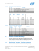
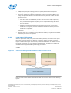
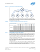


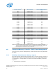
Table Of Contents
- Contents
- Revision History
- 1.0 Introduction
- 2.0 Interfaces
- 3.0 Technologies
- 3.1 Intel® Virtualization Technology (Intel® VT)
- 3.2 Intel® Trusted Execution Technology (Intel® TXT)
- 3.3 Intel® Hyper-Threading Technology (Intel® HT Technology)
- 3.4 Intel® Turbo Boost Technology 2.0
- 3.5 Intel® Advanced Vector Extensions 2.0 (Intel® AVX2)
- 3.6 Intel® Advanced Encryption Standard New Instructions (Intel® AES-NI)
- 3.7 Intel® Transactional Synchronization Extensions - New Instructions (Intel® TSX-NI)
- 3.8 Intel® 64 Architecture x2APIC
- 3.9 Power Aware Interrupt Routing (PAIR)
- 3.10 Execute Disable Bit
- 3.11 Supervisor Mode Execution Protection (SMEP)
- 4.0 Power Management
- 4.1 Advanced Configuration and Power Interface (ACPI) States Supported
- 4.2 Processor Core Power Management
- 4.3 Integrated Memory Controller (IMC) Power Management
- 4.4 PCI Express* Power Management
- 4.5 Direct Media Interface (DMI) Power Management
- 4.6 Graphics Power Management
- 5.0 Thermal Management
- 5.1 Desktop Processor Thermal Profiles
- 5.2 Thermal Metrology
- 5.3 Fan Speed Control Scheme with Digital Thermal Sensor (DTS) 1.1
- 5.4 Fan Speed Control Scheme with Digital Thermal Sensor (DTS) 2.0
- 5.5 Processor Temperature
- 5.6 Adaptive Thermal Monitor
- 5.7 THERMTRIP# Signal
- 5.8 Digital Thermal Sensor
- 5.9 Intel® Turbo Boost Technology Thermal Considerations
- 6.0 Signal Description
- 6.1 System Memory Interface Signals
- 6.2 Memory Reference and Compensation Signals
- 6.3 Reset and Miscellaneous Signals
- 6.4 PCI Express*-Based Interface Signals
- 6.5 Display Interface Signals
- 6.6 Direct Media Interface (DMI)
- 6.7 Phase Locked Loop (PLL) Signals
- 6.8 Testability Signals
- 6.9 Error and Thermal Protection Signals
- 6.10 Power Sequencing Signals
- 6.11 Processor Power Signals
- 6.12 Sense Signals
- 6.13 Ground and Non-Critical to Function (NCTF) Signals
- 6.14 Processor Internal Pull-Up / Pull-Down Terminations
- 7.0 Electrical Specifications
- 8.0 Package Mechanical Specifications
- 9.0 Processor Ball and Signal Information

— For package C-states, the processor is not required to enter C0 state before
entering any other C-state.
— Entry into a package C-state may be subject to auto-demotion – that is, the
processor may keep the package in a deeper package C-state than requested
by the operating system if the processor determines, using heuristics, that the
deeper C-state results in better power/performance.
The processor exits a package C-state when a break event is detected. Depending on
the type of break event, the processor does the following:
• If a core break event is received, the target core is activated and the break event
message is forwarded to the target core.
— If the break event is not masked, the target core enters the core C0 state and
the processor enters package C0 state.
— If the break event is masked, the processor attempts to re-enter its previous
package state.
• If the break event was due to a memory access or snoop request,
— But the platform did not request to keep the processor in a higher package C-
state, the package returns to its previous C-state.
— And the platform requests a higher power C-state, the memory access or
snoop request is serviced and the package remains in the higher power C-
state.
The following table shows package C-state resolution for a dual-core processor. The
following figure summarizes package C-state transitions.
Table 19. Coordination of Core Power States at the Package Level
Package C-State Core 1
C0 C1 C3 C6 C7
Core 0
C0 C0 C0 C0 C0 C0
C1 C0 C1
1
C1
1
C1
1
C1
1
C3 C0 C1
1
C3 C3 C3
C6 C0 C1
1
C3 C6 C6
C7 C0 C1
1
C3 C6 C7
Note: 1. If enabled, the package C-state will be C1E if all cores have resolved a core C1 state or higher.
Processor—Power Management
Desktop 4th Generation Intel
®
Core
™
Processor Family, Desktop Intel
®
Pentium
®
Processor Family, and Desktop Intel
®
Celeron
®
Processor Family
Datasheet – Volume 1 of 2 December 2013
56 Order No.: 328897-004