
Desktop 4th Generation Specification Sheet
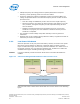
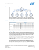


Table Of Contents
- Contents
- Revision History
- 1.0 Introduction
- 2.0 Interfaces
- 3.0 Technologies
- 3.1 Intel® Virtualization Technology (Intel® VT)
- 3.2 Intel® Trusted Execution Technology (Intel® TXT)
- 3.3 Intel® Hyper-Threading Technology (Intel® HT Technology)
- 3.4 Intel® Turbo Boost Technology 2.0
- 3.5 Intel® Advanced Vector Extensions 2.0 (Intel® AVX2)
- 3.6 Intel® Advanced Encryption Standard New Instructions (Intel® AES-NI)
- 3.7 Intel® Transactional Synchronization Extensions - New Instructions (Intel® TSX-NI)
- 3.8 Intel® 64 Architecture x2APIC
- 3.9 Power Aware Interrupt Routing (PAIR)
- 3.10 Execute Disable Bit
- 3.11 Supervisor Mode Execution Protection (SMEP)
- 4.0 Power Management
- 4.1 Advanced Configuration and Power Interface (ACPI) States Supported
- 4.2 Processor Core Power Management
- 4.3 Integrated Memory Controller (IMC) Power Management
- 4.4 PCI Express* Power Management
- 4.5 Direct Media Interface (DMI) Power Management
- 4.6 Graphics Power Management
- 5.0 Thermal Management
- 5.1 Desktop Processor Thermal Profiles
- 5.2 Thermal Metrology
- 5.3 Fan Speed Control Scheme with Digital Thermal Sensor (DTS) 1.1
- 5.4 Fan Speed Control Scheme with Digital Thermal Sensor (DTS) 2.0
- 5.5 Processor Temperature
- 5.6 Adaptive Thermal Monitor
- 5.7 THERMTRIP# Signal
- 5.8 Digital Thermal Sensor
- 5.9 Intel® Turbo Boost Technology Thermal Considerations
- 6.0 Signal Description
- 6.1 System Memory Interface Signals
- 6.2 Memory Reference and Compensation Signals
- 6.3 Reset and Miscellaneous Signals
- 6.4 PCI Express*-Based Interface Signals
- 6.5 Display Interface Signals
- 6.6 Direct Media Interface (DMI)
- 6.7 Phase Locked Loop (PLL) Signals
- 6.8 Testability Signals
- 6.9 Error and Thermal Protection Signals
- 6.10 Power Sequencing Signals
- 6.11 Processor Power Signals
- 6.12 Sense Signals
- 6.13 Ground and Non-Critical to Function (NCTF) Signals
- 6.14 Processor Internal Pull-Up / Pull-Down Terminations
- 7.0 Electrical Specifications
- 8.0 Package Mechanical Specifications
- 9.0 Processor Ball and Signal Information

Core C6 State
Individual threads of a core can enter the C6 state by initiating a P_LVL3 I/O read or
an MWAIT(C6) instruction. Before entering core C6 state, the core will save its
architectural state to a dedicated SRAM. Once complete, a core will have its voltage
reduced to zero volts. During exit, the core is powered on and its architectural state is
restored.
Core C7 State
Individual threads of a core can enter the C7 state by initiating a P_LVL4 I/O read to
the P_BLK or by an MWAIT(C7) instruction. The core C7 state exhibits the same
behavior as the core C6 state.
Note: C7 state may not be available on all SKUs.
C-State Auto-Demotion
In general, deeper C-states, such as C6 state, have long latencies and have higher
energy entry/exit costs. The resulting performance and energy penalties become
significant when the entry/exit frequency of a deeper C-state is high. Therefore,
incorrect or inefficient usage of deeper C-states have a negative impact on idle power.
To increase residency and improve idle power in deeper C-states, the processor
supports C-state auto-demotion.
There are two C-state auto-demotion options:
• C7/C6 to C3 state
• C7/C6/C3 To C1 state
The decision to demote a core from C6/C7 to C3 or C3/C6/C7 to C1 state is based on
each core’s immediate residency history and interrupt rate . If the interrupt rate
experienced on a core is high and the residence in a deep C-state between such
interrupts is low, the core can be demoted to a C3 or C1 state. A higher interrupt
pattern is required to demote a core to C1 state as compared to C3 state.
This feature is disabled by default. BIOS must enable it in the
PMG_CST_CONFIG_CONTROL register. The auto-demotion policy is also configured by
this register.
Package C-States
The processor supports C0, C1/C1E, C3, C6, and C7 (on some SKUs) power states.
The following is a summary of the general rules for package C-state entry. These
apply to all package C-states, unless specified otherwise:
• A package C-state request is determined by the lowest numerical core C-state
amongst all cores.
• A package C-state is automatically resolved by the processor depending on the
core idle power states and the status of the platform components.
— Each core can be at a lower idle power state than the package if the platform
does not grant the processor permission to enter a requested package C-state.
— The platform may allow additional power savings to be realized in the
processor.
4.2.5
Power Management—Processor
Desktop 4th Generation Intel
®
Core
™
Processor Family, Desktop Intel
®
Pentium
®
Processor Family, and Desktop Intel
®
Celeron
®
Processor Family
December 2013 Datasheet – Volume 1 of 2
Order No.: 328897-004 55