XP-M5S661GX Intel® Pentium® 4 LGA775 Processor Motherboard User's Manual 12MM-M5S661GX-1002R
Copyright Declaration © 2005 Gigatrend Technology Co., Ltd. All rights reserved. No part of this manual may be reproduced, copied, translated, or transmitted in any form or by any means without express permission from Gigatrend Technology. Companies and product names mentioned in this document are trademarks or registered trademarks of their respective owners.
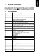
Contents Motherboard Layout ......................................................................... 4 1. Product Introduction .................................................................. 5 1.1. 1.2. Feature Summary ............................................................................. 5 I/O Back Panel and Connectors & Jumper Setting ......................... 6 1.2.1. I/O Back Panel ....................................................................................... 6 1.2.2.
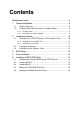
KB_MS ATX_12V COMA ATX FDD LPT CPU_FAN LAN SiS 661GX F_AUDIO XP-M5S661GX VGA LGA 775 R_USB USB AUDIO PCI1 IDE2 IDE1 CLR_CMOS IT8705AF PCI2 SiS 964 SATA1 BIOS PCI3 BATTERY CODEC CD_IN 4 SATA0 F_PANEL SUR_CEN F_USB1 F_USB2 PWR_LED SYS_FAN ICS1883 DDR2 AGP DDR1 English Motherboard Layout
English 1. Product Introduction The user manual provides steps related to quick installation. If you wish to view complete ", Open User Manual button located on the driver product information, please select the " CD or link to our website at http://www.axper.com to received the most up-to-date information. 1.1.
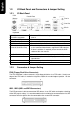
English 1.2. I/O Back Panel and Connectors & Jumper Setting 1.2.1. I/O Back Panel PS/2 Mouse Parallel Port LAN Line In USB Line Out Mic In PS/2 Keyboard COMA PS/2 Keyboard PS/2 Mouse connector Parallel port (LPT) COMA (Serial port) VGA Port USB (Universal Serial Bus Port) LAN (RJ45 LAN Port) Line In Line Out Mic In 1.2.2.
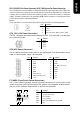
The cooler fan power connector supplies a +12V power voltage via a 3-pin/4-pin(only for CPU_FAN) power connector and possesses a ful-proof connection design. Most coolers are designed with color-coded power connector wires. A red power connector wire indicates a positive connection and requires a +12V power voltage. The black connector wire is the ground wire (GND). Please remember to connect the power to the cooler to prevent system overheating and failure.
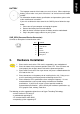
English PWR_LED Connects to the system power LED indicator whereby the power is indicated as ON or OFF. However, the indicator will flash when the system is suspended. PIN 1 1 SIGNAL MPD+ 2 MPD- 3 MPD- CLR_CMOS (Clear CMOS) You can clear the motherboard CMOS with the jumper to return your system to its initial status. To prevent improper usage, the jumper does not include the jumper plug. If you wish to use the Clear CMOS function, please short circuit the 1-2Pin.
The improper removal of the battery can result in harm. When replacing a battery, please make sure you use one that is of similar brand and model number. For information related to battery specifications and precautions, please refer to the manufacturer instructions. If you wish to delete the data stored in the CMOS, please follow the steps below: 1. Please turn off your computer and unplug the power. 2. Remove the battery from the motherboard. 3.
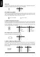
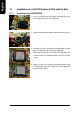
English 2.1. Installation of a LGA775 Pentium 4 CPU and Fan Sink 2.1.1. Installation of a LGA775 CPU 1. Push the socket lever arm down and away from the CPU socket and raise it up completely. 2. Open the load plate and gently remove the plastic cover. 3. Hold the CPU with your thumb and index fingers (do not touch the bottom of the CPU when holding it). Align notchs on the two sides of the CPU with the small sockets of the CPU socket and place the CPU straight down. 4.
English 2.1.2. Installation of Fan Sink 1. Apply a thin coating of thermal paste to complete cover the surface of the CPU. 2. Align the four fasteners of the fan sink with the four holes around the CPU socket. Push down each fastener and you should hear a "click" when the fastener is attached. Make sure the four fasteners are attached securely. Prior to installation of the fan sink, check the direction of each fastener by the arrow engraved on fastener top.
English 2.2. Installation of Memory 1. Before installing or removing memory, please make sure that the computer power is turned off to prevent hardware damage. 2. Please make sure that the memory used is supported by the motherboard. 3. Memory modules have a foolproof insertion design. The memory can be installed only when facing the correct position. If you cannot insert the module, please switch directions. 4. It is recommended that memory of similar capacity, specifications and brand be used.
English 3. BIOS Setup BIOS (Basic Input and Output System) stores all the information of the motherboard settings that is needed for system initiation as well as examining the CMOS. Its CMOS SETUP utility allows the user to make changes in BIOS configurations that are required or to activate certain features. The CMOS SETUP saves each item configuration in the CMOS SRAM of the motherboard. When the power is turned off, the battery on the motherboard supplies the required power to the CMOS SRAM.
English 5. Installation of SATA RAID Disks The Serial ATA channel controlled by the SiS 964 southbridge chip supports RAID 0 and RAID 1. This section explains the steps required to configure RAID disks. RAID (Redundant Array of Independent Disks) is a method of combining two hard disk drives into one logical unit. The advantage of an Array is to provide better performance or data fault tolerance. Hard disk drives can be combined together through a few different methods.
Creating RAID 1 5.4. Making the SATA RAID Driver Disk For the RAID disks to be recognized correctly during Windows Setup process, you need to install the SiS 964 SATA RAID driver at the beginning of Windows Setup. The procedure below introduces how to make a floppy disk containing the RAID driver. 1. Insert the Axper motherboard driver CD to the CD-ROM drive in your system. Go to My Computer and right-click the CD-ROM icon to select Open. 2. In the BootDrv folder, double-click the Menu.exe file.
English