
User's Manual
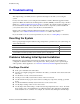
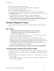
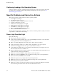

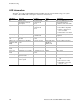
Table Of Contents
- About this Manual
- Manual Organization
- Product Accessories
- Additional Information and Software
- Safety Information
- Warnings
- Server Board Features
- Server Board Installations and Upgrades
- Server Utilities
- Troubleshooting
- Resetting the System
- Problems following Initial System Installation
- Hardware Diagnostic Testing
- Specific Problems and Corrective Actions
- Power Light Does Not Light
- No Characters Appear on Screen
- Characters Are Distorted or Incorrect
- System Cooling Fans Do Not Rotate Properly
- Diskette Drive Activity Light Does Not Light
- CD-ROM Drive or DVD-ROM Drive Activity Light Does Not Light
- Cannot Connect to a Server
- Problems with Network
- System Boots when Installing PCI Card
- Problems with Newly Installed Application Software
- Problems with Application Software that Ran Correctly Earlier
- Devices are not Recognized under Device Manager (Windows* Operating System)
- Hard Drive(s) are not Recognized
- Bootable CD-ROM Is Not Detected
- LED Information
- BIOS Error Messages
- Regulatory and Compliance Information
- Getting Help
- Intel® Server Issue Report Form
- Date Submitted:
- Company Name:
- Contact Name:
- Email Address:
- Intel Server Product:
- Priority (Critical, Hot, High, Low):
- Brief Problem Description. Provide a brief description below. See the last page for space to include a detailed problem description.
- Board / Chassis Information
- Operating System Information
- Operating System
- Version
- Service Pack
- Peripheral Information
- Hard Drive Information:
- Complete Problem Description

Troubleshooting
40 Intel Server Board SE7210TP1-E User Guide
LED Information
The Intel
®
Server Board SE7210TP1-E includes LEDs that can aid in troubleshooting your system.
A table of these LEDs with a description of their use is listed below.
LED Name Function Location Color Correction
ID Aid in server
identification from the
back panel
Front Panel and
board rear left
corner
Blue Press ID LED button or user
Server Management
software to turn off the LED.
System fault Visible fault warning Front panel and
board rear left
corner
Green or Amber
On = No Fault
Green Blink = degraded
Amber = critical error or
non-recoverable
Amber blink = non-critical
IDE activity Front panel Front panel and
board left side
Green Blinking = Activity. No action
required.
Memory fault
1–6
Identify failing memory
module
DIMM end front of
board
Amber On = Fault
POST code 1–4
(LSB, bit1, bit2,
MSB)
Display boot 80 POST
code
Left rear of board Each LED can be
Off, Green,
Amber, Red
See the POST code table
Fan Pack Fault Warn on fan failure Front center board Amber On = Fault
CPU 1 & 2 Fan
Fault
Identify fan failure Front center board Amber On = Fault
CPU 1 & 2
Fault
Identify processor failure 1” behind processor
socket
Amber On = Fault
5v Standby Identify 5v standby
power on state
Front left board Amber On = 5v standby power on
Power LED Identify the power state
of the system
Front Panel Green
Off = Power is off (off or
S5)
On = Power on or S0)
Slow Blink = Low power
state (S1 – S3)