
User's Manual
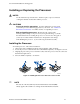
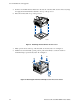
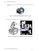

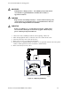
Table Of Contents
- About this Manual
- Manual Organization
- Product Accessories
- Additional Information and Software
- Safety Information
- Warnings
- Server Board Features
- Server Board Installations and Upgrades
- Server Utilities
- Troubleshooting
- Resetting the System
- Problems following Initial System Installation
- Hardware Diagnostic Testing
- Specific Problems and Corrective Actions
- Power Light Does Not Light
- No Characters Appear on Screen
- Characters Are Distorted or Incorrect
- System Cooling Fans Do Not Rotate Properly
- Diskette Drive Activity Light Does Not Light
- CD-ROM Drive or DVD-ROM Drive Activity Light Does Not Light
- Cannot Connect to a Server
- Problems with Network
- System Boots when Installing PCI Card
- Problems with Newly Installed Application Software
- Problems with Application Software that Ran Correctly Earlier
- Devices are not Recognized under Device Manager (Windows* Operating System)
- Hard Drive(s) are not Recognized
- Bootable CD-ROM Is Not Detected
- LED Information
- BIOS Error Messages
- Regulatory and Compliance Information
- Getting Help
- Intel® Server Issue Report Form
- Date Submitted:
- Company Name:
- Contact Name:
- Email Address:
- Intel Server Product:
- Priority (Critical, Hot, High, Low):
- Brief Problem Description. Provide a brief description below. See the last page for space to include a detailed problem description.
- Board / Chassis Information
- Operating System Information
- Operating System
- Version
- Service Pack
- Peripheral Information
- Hard Drive Information:
- Complete Problem Description

Server Installations and Upgrades
24 Intel Server Board SE7210TP1-E User Guide
Removing the Processor
To remove the processor, follow these instructions:
1. Observe the safety and ESD precautions at the beginning of this document.
2. Disconnect the processor fan cable.
3. Open the levers on the heat sink.
4. Disengage the retention mechanism hooks at the bottom of the heat sink.
5. Lift the heat sink from the processor.
6. Lift the processor lever.
7. Remove the processor.
Installing a PCI Card
Peripherals and add-in cards are not included in your system and must be purchased separately.
The PCI slots support full-height add-in cards or low profile PCI add-in cards. If a low profile card
is installed in the standard full-height riser card, it must be equipped with a standard full-height PCI
mounting bracket.
1. Remove the screw that attaches the PCI bracket shield to the rear of the chassis to remove the
shield. Retain the screw.
2. Insert the PCI card into the PCI slot. Tipping it in the slot while installing it may damage the
PCI card or slot.
3. Use the screw removed in step 1 to secure the PCI card to the chassis.
Replacing the Backup Battery
The lithium battery on the server board powers the RTC for up to 10 years in the absence of power.
When the battery starts to weaken, it loses voltage, and the server settings stored in CMOS RAM in
the RTC (for example, the date and time) may be wrong. Contact your customer service
representative or dealer for a list of approved devices.
WARNING
Danger of explosion if battery is incorrectly replaced. Replace only with
the same or equivalent type recommended by the equipment
manufacturer. Discard used batteries according to manufacturer’s
instructions.
ADVARSEL!
Lithiumbatteri - Eksplosionsfare ved fejlagtig håndtering. Udskiftning
må kun ske med batteri af samme fabrikat og type. Levér det brugte
batteri tilbage til leverandøren.