
User's Manual
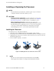
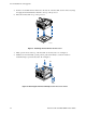
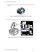

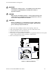
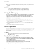
Table Of Contents
- About this Manual
- Manual Organization
- Product Accessories
- Additional Information and Software
- Safety Information
- Warnings
- Server Board Features
- Server Board Installations and Upgrades
- Server Utilities
- Troubleshooting
- Resetting the System
- Problems following Initial System Installation
- Hardware Diagnostic Testing
- Specific Problems and Corrective Actions
- Power Light Does Not Light
- No Characters Appear on Screen
- Characters Are Distorted or Incorrect
- System Cooling Fans Do Not Rotate Properly
- Diskette Drive Activity Light Does Not Light
- CD-ROM Drive or DVD-ROM Drive Activity Light Does Not Light
- Cannot Connect to a Server
- Problems with Network
- System Boots when Installing PCI Card
- Problems with Newly Installed Application Software
- Problems with Application Software that Ran Correctly Earlier
- Devices are not Recognized under Device Manager (Windows* Operating System)
- Hard Drive(s) are not Recognized
- Bootable CD-ROM Is Not Detected
- LED Information
- BIOS Error Messages
- Regulatory and Compliance Information
- Getting Help
- Intel® Server Issue Report Form
- Date Submitted:
- Company Name:
- Contact Name:
- Email Address:
- Intel Server Product:
- Priority (Critical, Hot, High, Low):
- Brief Problem Description. Provide a brief description below. See the last page for space to include a detailed problem description.
- Board / Chassis Information
- Operating System Information
- Operating System
- Version
- Service Pack
- Peripheral Information
- Hard Drive Information:
- Complete Problem Description
Server Installations and Upgrades
22 Intel Server Board SE7210TP1-E User Guide
5. If there is no thermal interface material on the bottom of the heat sink, use the enclosed syringe
and apply the thermal interface material to the top of the processor.
6. Place the fan heat sink on top of the processor.
TP00520
Figure 8. Attaching the Heat Sink to the Processor
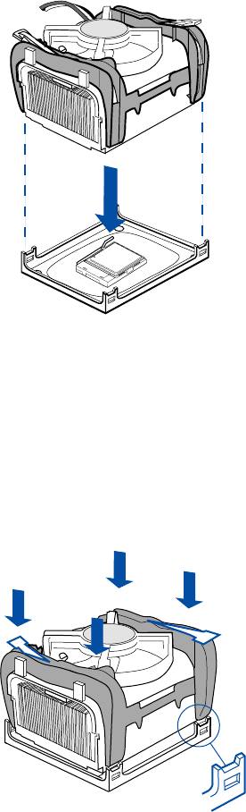
7. Fully open the levers at the top of the heat sink, as shown by letter “A” in Figure 9.
8. With the levers in their fully opened position, push down firmly to secure the retention
mechanism clips, represented by letter “B” in Figure 9.
TP00521
A
B
A
B
B
B
C
Figure 9. Attaching the Fan Heat Sink Clips to the Processor Socket