
User's Manual
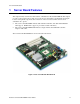
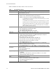
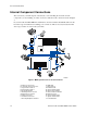
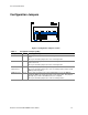

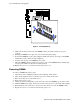
Table Of Contents
- About this Manual
- Manual Organization
- Product Accessories
- Additional Information and Software
- Safety Information
- Warnings
- Server Board Features
- Server Board Installations and Upgrades
- Server Utilities
- Troubleshooting
- Resetting the System
- Problems following Initial System Installation
- Hardware Diagnostic Testing
- Specific Problems and Corrective Actions
- Power Light Does Not Light
- No Characters Appear on Screen
- Characters Are Distorted or Incorrect
- System Cooling Fans Do Not Rotate Properly
- Diskette Drive Activity Light Does Not Light
- CD-ROM Drive or DVD-ROM Drive Activity Light Does Not Light
- Cannot Connect to a Server
- Problems with Network
- System Boots when Installing PCI Card
- Problems with Newly Installed Application Software
- Problems with Application Software that Ran Correctly Earlier
- Devices are not Recognized under Device Manager (Windows* Operating System)
- Hard Drive(s) are not Recognized
- Bootable CD-ROM Is Not Detected
- LED Information
- BIOS Error Messages
- Regulatory and Compliance Information
- Getting Help
- Intel® Server Issue Report Form
- Date Submitted:
- Company Name:
- Contact Name:
- Email Address:
- Intel Server Product:
- Priority (Critical, Hot, High, Low):
- Brief Problem Description. Provide a brief description below. See the last page for space to include a detailed problem description.
- Board / Chassis Information
- Operating System Information
- Operating System
- Version
- Service Pack
- Peripheral Information
- Hard Drive Information:
- Complete Problem Description
Server Board Features
Intel Server Board SE7210TP1-E User Guide 15
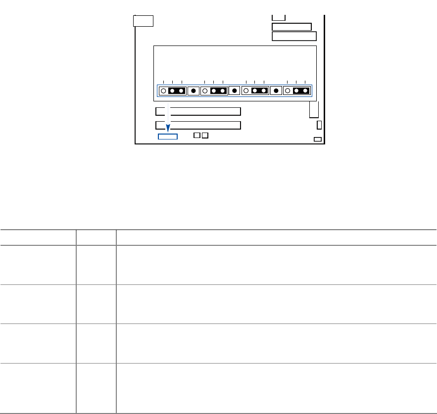
Configuration Jumpers
Figure 4. Configuration Jumper Location
Table 2. Configuration Jumper [J1D1]
Jumper Name Pins What happens at system reset…
CMOS clear 2-3 If these pins are jumpered, the CMOS settings will be cleared on the next
reset.
These pins should be jumpered on 1-2 for normal operation.
Password Clear 6-7 If these pins are jumpered, administrator and user passwords will be cleared
on the next reset.
These pins should be jumpered on 5-6 for normal operation.
BIOS Flash
Write Protect
11-12 If these pins are jumpered, it is possible to update the BIOS Boot Block code.
These pins should be jumpered on 10-11 for normal operation and for normal
BIOS operational updates.
BIOS Recovery 14-15 If these pins are jumpered, the system will attempt to recover the BIOS by
loading the BIOS code into the flash device from a floppy disk. This jumper is
typically only used when the BIOS has become corrupted.
These pins should be jumpered on 13-14 for normal operation.
J1D1
12356791011131415
TP00630