
User's Manual
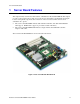
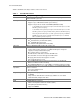
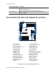
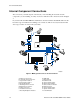
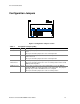
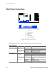
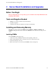
Table Of Contents
- About this Manual
- Manual Organization
- Product Accessories
- Additional Information and Software
- Safety Information
- Warnings
- Server Board Features
- Server Board Installations and Upgrades
- Server Utilities
- Troubleshooting
- Resetting the System
- Problems following Initial System Installation
- Hardware Diagnostic Testing
- Specific Problems and Corrective Actions
- Power Light Does Not Light
- No Characters Appear on Screen
- Characters Are Distorted or Incorrect
- System Cooling Fans Do Not Rotate Properly
- Diskette Drive Activity Light Does Not Light
- CD-ROM Drive or DVD-ROM Drive Activity Light Does Not Light
- Cannot Connect to a Server
- Problems with Network
- System Boots when Installing PCI Card
- Problems with Newly Installed Application Software
- Problems with Application Software that Ran Correctly Earlier
- Devices are not Recognized under Device Manager (Windows* Operating System)
- Hard Drive(s) are not Recognized
- Bootable CD-ROM Is Not Detected
- LED Information
- BIOS Error Messages
- Regulatory and Compliance Information
- Getting Help
- Intel® Server Issue Report Form
- Date Submitted:
- Company Name:
- Contact Name:
- Email Address:
- Intel Server Product:
- Priority (Critical, Hot, High, Low):
- Brief Problem Description. Provide a brief description below. See the last page for space to include a detailed problem description.
- Board / Chassis Information
- Operating System Information
- Operating System
- Version
- Service Pack
- Peripheral Information
- Hard Drive Information:
- Complete Problem Description
Server Board Features
Intel Server Board SE7210TP1-E User Guide 13
Server Board Features (continued)
Power Management Support for ACPI:
Suspend to RAM (STR)
Wake on USB, PCI, RS-232, PS/2, LAN, and front panel
Server Management
Intel
®
Server Management 5.8 support via mini Baseboard Management
Controller (mBMC)
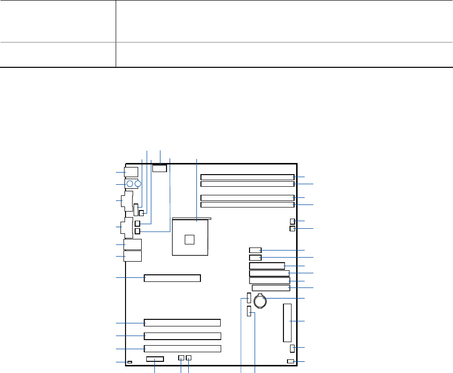
Server Board Connector and Component Locations
K
M
AA
BB
CC
DD
EE FF
GG
HH
II
JJ
KK
LL
MM
NN
OO
PP
QQ
RR
SS
TT
UU
VV
WWXXYYZZAAAA
BBBB
CCFF
DDGG
EEHH
FFII
GGJJ
HHKK
IILL
TP00507
CC
DD
EE
A: Serial B Header
B: CPU Fan Header
C: Sys Fan Header 3
D: +12 V CPU Power Connector
E: Sys Fan Header 4
F: Processor Socket
G: DIMM 2B Socket
H: DIMM 2A Socket
I: DIMM 1B Socket
J: DIMM 1A Socket
K: Sys Fan Header 1
L: Sys Fan Header 2
M: Front Panel USB Header
N: Aux Power Connector
O: Main Power Connector
P: Secondary IDE Connector
Q: Primary IDE Connector
R: Floppy Connector
S: Battery
T: Front Panel Connector
U: Hot Swap Backplane Header
V: SCSI LED Header
W: SATA-A1 Connector
X: SATA-A2 Connector
Y: Sys Fan Header 6
Z: Sys Fan Header 5
AA: Jumper Block
BB: Chassis Intrusion Header
CC: PCI-X Slot 1, 64/66 RAIDIOS
DD: PCI-X Slot 2, 64/66
EE: PCI-X Slot 3, 64/66
FF: PCI Slot 6, 32/33
GG: NIC 2 (10/100 Mbit)
HH: NIC 1 (1 Gbit)
II: Video Connector
JJ: Serial A Connector
KK: Keyboard and Mouse
LL: USB Connectors
Figure 2. Intel Server Board SE7210TP1-E Layout